Cisco 4948 Installation Guide - Page 20
Feature, Description, The Catalyst 4948E switch provides a 10/100/1000 RJ-45 port Ethernet - configuration guide
 |
UPC - 746320908878
View all Cisco 4948 manuals
Add to My Manuals
Save this manual to your list of manuals |
Page 20 highlights
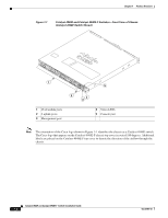
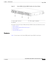
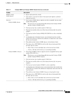
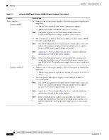
Features Chapter 1 Product Overview Table 1-1 Catalyst 4948E and Catalyst 4948E-F Switch Features Feature Chassis (both chassis) Uplink ports (both chassis) Downlink ports (both chassis) Console port (both chassis) Ethernet management port (both chassis) Description 1-RU, 48 10/100/1000 ports plus 4 1-GB/10-GB ports, fixed configuration switch with redundant power supplies The chassis has 4 1-GB or 10-GB uplink ports. An SFP or SFP+ transceiver must be installed in the chassis port socket for the port to operate. Cable type and recommended cabling distance for each port is determined by the type of SFP or SFP+ transceiver installed in the uplink port. A bicolor port link status LED is associated with each uplink port. LED colors indicate the following status: • Green-The link is established and operational. • Amber-The port is disabled. • Blinking amber-The system has detected a fault with the link. • Off-No link is established or the transceiver is not installed in the port socket. See Appendix B, "Transceiver, Chassis Connectors, and Cable and Adapter Specifications" for supported SFP and SFP+ transceiver descriptions, specifications, and cabling distances. • The chassis has 48 10/100/1000BASE autonegotiating-capable downlink ports. Each port has an RJ-45 connector. A bicolor port link status LED is associated with each port. LED colors indicate the following status: • Green-The link is established and operational. • Amber-The port is disabled. • Blinking amber-The system has detected a fault with the link. • Off-No link is established or no network interface cable is installed. A console serial port (RJ-45) is provided for switch management using standard console equipment. Additional information including a connector pinout table is provided in Appendix B, "Transceiver, Chassis Connectors, and Cable and Adapter Specifications" for the console port. Note A console cable is not provided in the accessory kit. It can be ordered as an option. • The Catalyst 4948E switch provides a 10/100/1000 RJ-45 port Ethernet Management port that can be used to manage the switch through an Ethernet network. This port can also be used to download software to the switch or transfer files to remote servers for analysis or backup storage. • The typical connection to the Management Ethernet port uses an Ethernet cable with RJ-45 connectors at each end. The other end of the cable typically connects to an Ethernet switch, hub, or router that provides connectivity between the multishelf system and networks from which system management is desired. Appendix B, "Transceiver, Chassis Connectors, and Cable and Adapter Specifications" contains additional information for the Ethernet management port including a connector pinout table. Catalyst 4948E and Catalyst 4948E-F Switch Installation Guide 1-4 OL-21561-02
-
 1
1 -
2
-
3
-
4
-
5
-
6
-
7
-
8
-
9
-
10
-
11
-
12
-
13
-
14
-
 15
15 -
 16
16 -
 17
17 -
 18
18 -
 19
19 -
 20
20 -
 21
21 -
 22
22 -
 23
23 -
 24
24 -
 25
25 -
26
-
27
-
28
-
29
-
30
-
31
-
32
-
33
-
34
-
35
-
36
-
37
-
38
-
39
-
40
-
41
-
42
-
43
-
44
-
45
-
46
-
47
-
48
-
49
-
50
-
51
-
52
-
53
-
54
-
55
-
56
-
57
-
58
-
59
-
60
-
61
-
62
-
63
-
64
-
65
-
66
-
67
-
68
-
69
-
70
-
71
-
72
-
73
-
74
-
75
-
76
-
77
-
78
-
79
-
80
-
81
-
82
-
83
-
84
-
85
-
86
-
87
-
88
-
89
-
90
-
91
-
92
-
93
-
94
-
95
-
96
-
97
-
98
-
99
-
100
-
101
-
102
-
103
-
104
-
105
-
106
-
107
-
108
-
109
-
110
-
111
-
112
-
113
-
114
-
115
-
116
-
117
-
118
-
119
-
120
-
121
-
122
-
123
-
124
-
125
-
126
-
127
-
128
-
129
-
130
-
131
-
132
-
133
-
134
-
135
-
136
-
137
-
138
-
139
-
140
-
141
-
142
-
143
-
144
-
145
-
146
-
147
-
148
-
149
-
150
-
151
-
152
-
153
-
154
-
155
-
156
-
157
-
158
-
159
-
160
-
161
-
162
 |
 |