Cisco 4948 Installation Guide - Page 30
Site Requirements, Rack-Mounting Guidelines - poe
 |
UPC - 746320908878
View all Cisco 4948 manuals
Add to My Manuals
Save this manual to your list of manuals |
Page 30 highlights
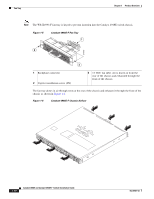
Site Requirements Chapter 2 Preparing for Installation Warning Voltages that present a shock hazard may exist on Power over Ethernet (PoE) circuits if interconnections are made using uninsulated exposed metal contacts, conductors, or terminals. Avoid using such interconnection methods, unless the exposed metal parts are located within a restricted access location and users and service people who are authorized within the restricted access location are made aware of the hazard. A restricted access area can be accessed only through the use of a special tool, lock and key or other means of security. Statement 1072 Site Requirements These following sections describe some of the basic site requirements that you should be aware of as you prepare to install your Catalyst 4948E or Catalyst 4948E-F switch: • Rack-Mounting Guidelines, page 2-2 • Temperature, page 2-3 • Air Flow, page 2-4 • Humidity, page 2-5 • Altitude, page 2-5 • Dust and Particulates, page 2-5 • Corrosion, page 2-6 • Electromagnetic and Radio Frequency Interference, page 2-6 • Shock and Vibration, page 2-7 • Maintaining Safety with Electricity, page 2-9 • Preventing Electrostatic Discharge Damage, page 2-10 Rack-Mounting Guidelines A rack-mount kit (69-2037-xx) is included in the accessory kit for mounting the switch in a standard 19-inch (48.3 cm) equipment rack. This rack-mount kit is not suitable for use in the following situations: • Racks with obstructions (such as power strips) that could impair access to the switch Before rack-mounting the switch, ensure the following: • The equipment rack is the proper size. - The width of the rack, between the two front-mounting strips or rails, must be 17.75 inches (45.09 cm). - The depth of the rack, between the front- and rear-mounting strips, must be at least 19.25 inches (48.9 cm) but not more than 32.5 inches (82.5 cm). - The rack must have sufficient vertical clearance to insert the chassis. The chassis height is 1 U (1.75 inches (4.45 cm)). • The equipment rack is stable and in no danger of falling over. - Ensure that the shelf is constructed to support the weight and dimensions of the chassis. - We recommend that you bolt the rack to the floor. - Mount the unit at the bottom of the rack if it is the only unit in the rack. Catalyst 4948E and Catalyst 4948E-F Switch Installation Guide 2-2 OL-21561-02
-
 1
1 -
2
-
3
-
4
-
5
-
6
-
7
-
8
-
9
-
10
-
11
-
12
-
13
-
14
-
15
-
16
-
17
-
18
-
19
-
20
-
21
-
22
-
23
-
24
-
 25
25 -
 26
26 -
 27
27 -
 28
28 -
 29
29 -
 30
30 -
 31
31 -
 32
32 -
 33
33 -
 34
34 -
 35
35 -
36
-
37
-
38
-
39
-
40
-
41
-
42
-
43
-
44
-
45
-
46
-
47
-
48
-
49
-
50
-
51
-
52
-
53
-
54
-
55
-
56
-
57
-
58
-
59
-
60
-
61
-
62
-
63
-
64
-
65
-
66
-
67
-
68
-
69
-
70
-
71
-
72
-
73
-
74
-
75
-
76
-
77
-
78
-
79
-
80
-
81
-
82
-
83
-
84
-
85
-
86
-
87
-
88
-
89
-
90
-
91
-
92
-
93
-
94
-
95
-
96
-
97
-
98
-
99
-
100
-
101
-
102
-
103
-
104
-
105
-
106
-
107
-
108
-
109
-
110
-
111
-
112
-
113
-
114
-
115
-
116
-
117
-
118
-
119
-
120
-
121
-
122
-
123
-
124
-
125
-
126
-
127
-
128
-
129
-
130
-
131
-
132
-
133
-
134
-
135
-
136
-
137
-
138
-
139
-
140
-
141
-
142
-
143
-
144
-
145
-
146
-
147
-
148
-
149
-
150
-
151
-
152
-
153
-
154
-
155
-
156
-
157
-
158
-
159
-
160
-
161
-
162
 |
 |