Craftsman #10402 Operation Manual
Craftsman #10402 - Professional Laser 10 in. Radial Arm Saw 22010 Manual
 |
View all Craftsman #10402 manuals
Add to My Manuals
Save this manual to your list of manuals |
Craftsman #10402 manual content summary:
- Craftsman #10402 | Operation Manual - Page 1
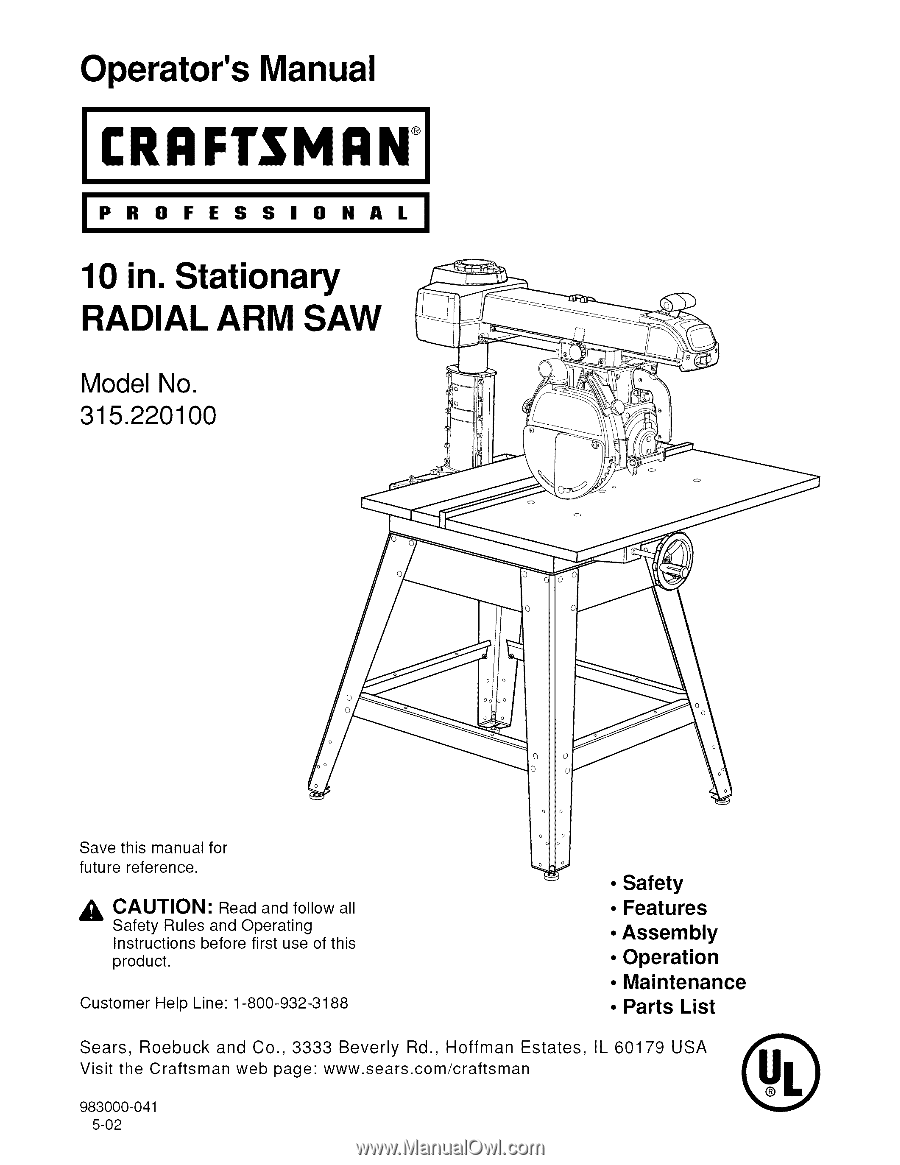
all Safety Rules and Operating Instructions before first use of this product. Customer Help Line: 1-800-932-3188 • Safety • Features • Assembly • Operation • Maintenance • Parts List Sears, Roebuck and Co., 3333 Beverly Rd., Hoffman Estates, IL 60179 USA Visit the Craftsman web page: www.sears.com - Craftsman #10402 | Operation Manual - Page 2
CRAFTSMAN RADIAL ARM SAW If this product fails due to a defect in material or workmanship within one year from the date of purchase, Sears will repair it, free of charge, Contact a Sears Service through this entire operator's manual before using your new ...• Loose Parts List ...• Tools Needed ...• - Craftsman #10402 | Operation Manual - Page 3
...Leveling the Table Supports ...Installing the Front Table Other Cuts ...Cutting Long Workpieces ...Non-Through Cuts ...• Laser Guide ... 23 24 25 25 26 26 27 28 28- Troubleshooting ...• Exploded View and Repair Parts List ...• Parts Ordering / Service ... 58-62 64-85 back page - Craftsman #10402 | Operation Manual - Page 4
repair. Always use original factory replacement parts when servicing. If you have questions about terms in the following rules, refer to the Glossary of Terms for Woodworking or the Features section, READ ALL INSTRUCTIONS • KNOW YOUR POWER TOOL. Read the operator's manual carefully, Learn the saw - Craftsman #10402 | Operation Manual - Page 5
WHEN SERVICING, use only identical Sears replacement parts. Use of any other parts may create a hazard or damage product, • NEVER USE THIS TOOL IN AS A SUBSTITUTE FOR A TABLE if additional support is needed, Use a support the same height as the table, • USE A SUPPORT FOR THE SIDES AND BACK OF THE SAW - Craftsman #10402 | Operation Manual - Page 6
. Always use a fence or straight edge guide when ripping. • BE SURE THE BLADE blade guard, NEVER TOUCH BLADE or other moving parts during use, for any reason, • ALLOW INSTRUCTIONS. Refer to them frequently and use to instruct other users, If you loan someone this tool, loan them these instructions - Craftsman #10402 | Operation Manual - Page 7
blade. • NEVER LOWER AN UNLOCKED REVOLVING CUTTING TOOL. Always lock the carriage lock knob before lowering injured, • POSITION THE CUT SO THE WASTE PART FALLS OFF. Never use a length stop on the the saw, locate the source, and correct the problem before using the saw further, • POSITION THE CUT - Craftsman #10402 | Operation Manual - Page 8
is heavy enough for a short distance will be too light for a greater distance. A line that can support one power tool may not be able to support two or three tools. GROUNDING INSTRUCTIONS In the event of a malfunction or breakdown, grounding provides a path of least resistance for electric current - Craftsman #10402 | Operation Manual - Page 9
See Figures 3 and 4, • Reinstall motor cover. • Replace the 120V plug on the main cord with a UL listed 240V, 15 amp, 3-prong plug, • Follow the instructions provided with the UL listed plug, • Plug the cord into a 240V, 15 amp, 3-blade receptacle. Make sure the receptacle is connected to a 240V AC - Craftsman #10402 | Operation Manual - Page 10
cut removing a wedge from a block so the end (or part of it) is angled rather than at 90 degrees. Climb A to help guide workpieces during rip cuts. Fence A piece of wood used as a edge guide for the End The end of the workpiece pushed into the cutting tool first. Miter Cut A vertical cut made at any - Craftsman #10402 | Operation Manual - Page 11
. itto powersupply.Thesawshouldneverbe connectedto thepowersupplywhenyouare • Donotdiscardthepackingmaterialsuntilyouhave carefullyinspectedthesaw,identifiedall parts,and assemblingparts,makingadjustmentsin, stalling satisfactoriloyperatedyournewsaw, or removingbladeso, r whennotin - Craftsman #10402 | Operation Manual - Page 12
Check all loose parts from the box with the list below, Use the instructions on the following pages to assemble. All fasteners are shown actual size, 1, Saw Assembly 1 SAW ASSEMBLYSHOWNAS PACKED 2, Elevating Handwheel A, Handwheel 1 B. Screw (10-24 x 5/8 in. Soc, - Craftsman #10402 | Operation Manual - Page 13
Check aH bose parts from the box with the Hst bebw. Use the instructions on the following pages to assembb. AH fasteners are shown actual size. . Saw Base to Leg Stand AssemMy A. Saw AssemMy (not shown 1 B, Leg Stand AssemMy ( - Craftsman #10402 | Operation Manual - Page 14
Check aH Uoose parts from the box with the Hst beUow. Use the instructions on the following pages to assemMe. AH fasteners are shown actuaUsize, 12. TaMe Support A. TaMe Support Rails 2 B. Square Head BoUt(5/18-18 x 3/4 in 4 C. Fiat Washer (5/18 in 4 D. Lock Washer (5/16 in 4 E. Hex Nut (5/18- - Craftsman #10402 | Operation Manual - Page 15
The following tools are needed for assembly and alignment. They are not included with this saw. HEXKEYS: 5/32in. AND 1/8in, LEVEL MEDIUMFLAT BLADE SCREWDRIVER PHILLIPSSCREWDRIVER PENCIL SMALL HAMMER CHANNELLOCK PLIERS PUERS FRAMINGSQUARE 15 - Craftsman #10402 | Operation Manual - Page 16
own safety, Read and understand owner's manual before operating saw. • This tool has more than one connection to the power source. • To reduce the risk of electrical shock or injury, disconnect all power connections • When servicing, use only identical replacement parts. • Para su seguridad, lea - Craftsman #10402 | Operation Manual - Page 17
guarding. • Provide proper workpiece support • Position cutting tool behind the fence. • With power off and switch key removed, turn cutting tool by hand to make sure it does not strike guard, fence or any other saw parts. • Para su seguridad, lea y entienda el manual del propietario antes de operar - Craftsman #10402 | Operation Manual - Page 18
yoke fits into a carriage on the arm, which can travel back and forward. The yoke supports the yoke assembly (motor, blade, and blade guard) and can be pivoted so the blade with all operating features and safety requirements of your Sears Craftsman Radial Arm Saw. *Shown on following pages ARM - Craftsman #10402 | Operation Manual - Page 19
The assembly extending from the column, which supports the yoke, the motor, and the - For maximum performance, use the Craftsman 40-tooth, 10 in. carbide the Accessory section of this manual. The blade is powered by keep each item in place unless specifically instructed to move it. See Figures 9A and - Craftsman #10402 | Operation Manual - Page 20
front) that changes the height of the arm and the blade. See Figure 9C. FENCE - Removable guide for work, which extends across width of table. See Figure 9C. FRONT TABLE - Fixed portion of the worktable that supports the work. See Figure 9C. HANDLE - Used to pull the yoke assembly. Mounted on the - Craftsman #10402 | Operation Manual - Page 21
OFF, remove the yellow key. Place the key in a location that is inaccessible to children and others not qualified to use the tool. See Figures 9A and 9C. YOKE - Supports the blade and motor. Can be pivoted to index the blade between rip and cross cuts. Located between the carriage and the - Craftsman #10402 | Operation Manual - Page 22
in the leg stand carton: 4 leveling feet 8 large hex nuts (3/8-16) [] Obtain four legs and eight braces from the leg stand carton. See the Loose Parts section. SHORT LOWERBRACE SHORT BRACE _TAR WASHER [] Place a 3/8-16 hex nut on each leveling foot and insert leveling feet into the bottom of the - Craftsman #10402 | Operation Manual - Page 23
MOUNTING SAW TO LEG STAND See Figure ! 1. _ WARNING: Firmly bolt the saw to the leg stand to keep the saw from tipping, walking, or sliding. [] Locate the following hardware from a small hardware bag: 4 hex bolts (5/16-18 x 5/8 in.) 4 Iockwashers (5t16 in.) 8 flat washers (11/32 in.) 4 hex nuts (5/ - Craftsman #10402 | Operation Manual - Page 24
13A- 13C. The yoke rides in the carriage below the arm and supports the motor, the blade guard, and the blade. Install the yoke lockwasher. Do not risk serious injury or damage to the saw by failing to replace these parts. [] Tighten the carriage lock knob, on the carriage cover on the left of the - Craftsman #10402 | Operation Manual - Page 25
inserted from within the saw base outward. [] Place a flat washer, a lock washer, and a hex nut on the end of each screw. [] Position table supports so that bolts are approximately centered in slotted holes. [] Finger tighten or snug with a 1/2 in. wrench only at this time. Final adjustments will be - Craftsman #10402 | Operation Manual - Page 26
SETTING THE ARM LOCK KNOB See Figure 16. it may be possible to move the arm when locked, if the arm lock knob is too loose. If the arm does not move freely when unlocked, the arm lock knob may be too tight. Use this procedure to check and set the arm lock knob by turning the arm lock wheel (under - Craftsman #10402 | Operation Manual - Page 27
SETTING THE BEVEL LOCK LEVER See Figures 18A- 18C. The bevel lock lever locks the blade at desired angles other than the preset positive stop angles. The bevel lock lever is preset at the factory but may need readjustment after shipping or extended use. Check for overtightness or looseness and make - Craftsman #10402 | Operation Manual - Page 28
result in a poor cut or difficulty in elevating the carriage. The coJumn tube is the upper portion of the column and extends from the column support. Note: It is critical to remove alJ looseness with this procedure. If this procedure is not done correctly, folJowing adjustments will be wrong and - Craftsman #10402 | Operation Manual - Page 29
the rotation adjustment. OthenMse, raise and lower the arm with the elevating hand= wheel. Tighten the black screws on the right side of the column support by 1/16th to l/8th of a turn. Tighten the two silver screws on the left side slightly more. You will need two 1/2 in. wrenches or sockets - Craftsman #10402 | Operation Manual - Page 30
ADJUSTING THE CARRIAGE BEARINGS See Figures 21A - 21B. Loose carriage bearings permit the blade to wander slightly while cutting, which will result in a poor cut and more wear and tear on the saw. Use the following steps to check for tightness and to then adjust the bearings if needed. [] On the - Craftsman #10402 | Operation Manual - Page 31
22A. [] Lock the arm lock knob and the carriage lock knob. [] Using one of the blade wrenches as a feeler gage, place it on the table support below the arbor shaft. [] With the elevating handwheel, carefully lower the motor until the shaft just touches the wrench. The wrench should move with only - Craftsman #10402 | Operation Manual - Page 32
in. long pan head screw in the four remaining holes and through the holes in the support. Cap with a lock washer and hex nut. Tighten with a 7/16 in. wrench and . See Figure 23B. [] Place the table, top up, on the table supports so the center counterbored hole lines up over the hole in the U-clip. - Craftsman #10402 | Operation Manual - Page 33
is inserted in the wrong end of the bracket, the clamp will not work. [] Place the clamp bracket into the rectangle holes in the table support. Hold the cup washer against the rear table and turn the thumbscrew clockwise until it snaps into the cup washer. [] Tighten the thumbscrews to clamp - Craftsman #10402 | Operation Manual - Page 34
THUMBSCREW CLAMP BRACKET SQUARENUT CUP WASHER CLAMPSHOWN 1 ASSEMBLED SLOT Fig. 25B RECTANGLE HOLE TO LOOSEN CUP WASHER TABLE SUPPORT _NSTALUNG BLADE AND BLADE GUARD See Figures 26A - 26C. [] Collect the blade and hardware that were removed earlier. Place the inner blade washer, saw - Craftsman #10402 | Operation Manual - Page 35
between the motor and the column. Lock the yoke lock handle. [] With the elevating handwheeJ, lower the arm until the blade just clears the table. [] Support the lower outer blade guard and loosen the carriage lock knob on the left of the arm. Move the yoke back until the blade touches - Craftsman #10402 | Operation Manual - Page 36
_NSTALLING RiP SCALE _ND_CATORS See Figure 28. The rip scale indicators on the arm show the distance between the blade and the rip fence with the fence in the front and rear positions. The upper scale is used when the fence is positioned directly behind the front table. The lower scale is used when - Craftsman #10402 | Operation Manual - Page 37
ALIGNING THE ARM FOR CROSS CUTS See Figures 29,4 - 29C. This procedure checks whether the arm is exactly 0 ° for cross cut travel by checking the blade against the table and the miter indicator. Remove the rear table, spacer table, and fence, but leave the front table in place. You will need a - Craftsman #10402 | Operation Manual - Page 38
ALIGNING BLADE TO TABLE AT 0 ° BEVEL See Figures 30A - 30D, This procedure squares the blade to the table at 0 ° bevel (vertical) so the blade angle will be accurate. If the blade is not at 0 ° bevel, follow the steps below to rotate slightly, You will need a framing square and a 1/4 in, hex key, • - Craftsman #10402 | Operation Manual - Page 39
the yoke lock handle. Retighten the two hex bolts on the yoke pivot latch. • Replace the carriage cover. • Loosen the carriage lock knob and guide the yoke assembly to the back of the arm. SAW VIEWED FROM ABOVE , NEEDED " BLADE _ _ADJUSTMENT NO ADJUSTMENTNEEDED FENCE FRAMING SQUARE BLADE GAP - Craftsman #10402 | Operation Manual - Page 40
PARALLELING BLADE TO TABLE See Figures 32A - 32C. This procedure squares the blade to the table at 90 ° bevel so horizontal cuts will be accurate. This also reduces kickback, as well as splintering and burning of the cut edges of the workpiece. If the blade is not at 90 ° bevel, follow the steps to - Craftsman #10402 | Operation Manual - Page 41
, Lock the yoke lock handle. • With the elevating handwheel, lower the arm until the blade just clears the table. • Loosen the carriage lock knob and guide the blade back to just touch the fence, Tighten the carriage lock knob. IN-RIPSCALE ONRIGHTSIDE OF ARM • On the right side of the arm - Craftsman #10402 | Operation Manual - Page 42
left side of the control cut housing, ,_ WARNING: Do not use the saw without the control cut and blade guards in place unless specifically instructed to do so. Otherwise uncontrolled contact with the blade could occur, resulting in personal injury, • Plug in the control cut cord, leaving the main - Craftsman #10402 | Operation Manual - Page 43
should be aligned according to the procedures outlined in the Adjustments Section of this manual, • Using a two-foot length of 1 x 12 in, board and fine line perpendicular to the edge of the board using the fence as a guide. Position the marked board against the fence, • With the guard in place, - Craftsman #10402 | Operation Manual - Page 44
Check with an electrician or service personnel if you are unsure Refer to the Electrical page of this manual, TYPES OF CUTS See Figure 36, made with the blade vertical or beveled, Instructions for making each kind of cut are and your safety, do not use the laser guide during any rip cuts. In rip cuts, - Craftsman #10402 | Operation Manual - Page 45
is inaccessible to children and others not qualified to use the tool. L INSERTSWITCHKEY Fig. 37 SWITCHON Fig. 38 CAUSES OF KICKBACK -set blades. Never make cuts with dull blades. • To avoid pinching the blade, support the work properly before beginning a cut. • When making a cut, use steady, - Craftsman #10402 | Operation Manual - Page 46
blade is between 1/2 in. and 2 in. from the fence. (If the cut is narrower than 1/2 in., use a different saw.) Refer to the drawings and instructions provided so you can make safer and more precise cuts. PUSHSTICKS See Figure 40. Pushsticks must be narrower than the workpiece, with a 90 ° notch in - Craftsman #10402 | Operation Manual - Page 47
MAKING A CROSS CUT See Figure 43. Use this procedure to make a cut with the blade vertical and straight forward, If a kerf does not exist for the line of the cut (cutting path), follow the steps to make one, Each cutting path requires its own kerf, ,_ WARNING: Make sure the blade guard is lowered - Craftsman #10402 | Operation Manual - Page 48
See Figure 44. In a miter cut, the blade is vertical and the arm angled, If a kerf does not exist for the cutting path, make one (instructions below). Each cutting path requires its own kerf, ,_ WARNING: Make sure the blade guard is lowered and is working properly to prevent possible injury. Always - Craftsman #10402 | Operation Manual - Page 49
MAKING A BEVEL CUT See Figure 45. This procedure makes a cut with the blade and motor angled and the arm straight (90 ° to fence), If there is no kerf, follow the steps to make one, Try this cut on scrap wood before cutting your workpiece, ,A, WARNING: Make sure the blade guard is lowered and is - Craftsman #10402 | Operation Manual - Page 50
MAKING A COMPOUND CROSS CUT See Figure 46. In this cut, both the blade and the arm are angled, Be familiar with both bevel and miter cuts before making a compound cut, Practice on scrap wood, ,_ WARNING: Make sure the blade guard is lowered and is working properly to prevent possible injury, Always - Craftsman #10402 | Operation Manual - Page 51
• Always set up the workpiece so the wider part of the wood is between the blade and the better accuracy, and your safety, do not use the laser guide during any rip cuts, A precise and safe rip cut clearance, Instructions are given for an in-rip cut. At certain points, the instructions will - Craftsman #10402 | Operation Manual - Page 52
under the lower set of pawls.) • Remove the workpiece from the table, Set the push block, featherboard, or pushstick nearby, • Set up table extension(s) and supports. • Keep your other hand on the table and steady the workpiece against the fence. Keep that hand at least 8 in. from the blade, • If - Craftsman #10402 | Operation Manual - Page 53
and non-through cuts. When making one of the following cuts, follow the instructions that apply for the basic cut, depending on the position, shape, and size to full speed before it contacts the wood. See Figure 49. • Place a support the same height as the saw table nearby for the cut work. • When - Craftsman #10402 | Operation Manual - Page 54
saw with the switch on the arm to confirm the blade is not receiving power. • Remove the blade and blade guard (see Assembly section), • Place a support the same height as the saw table nearby for the cut work. Lower the blade with the elevating handwheel, • Make sure the wood is not - Craftsman #10402 | Operation Manual - Page 55
Blade" in the Assembly section of this operator's manual,) Note: The laser guide replaces the outer blade washer. • Position flat surface of laser guide against the blade. Warning labels are visible when laser guide is mounted properly, • Secure laser guide using blade nut provided, • Hold the blade - Craftsman #10402 | Operation Manual - Page 56
is running and the laser guide is mounted on the saw. After cleaning laser guide and replacing batteries, secure laser guide cover to laser guide support using the two phillips . APERTURE LASERGUIDE ,_ DANGER: Laser radiation when open and interlock defeated. AVOID DIRECT EYE EXPOSURE, CRRFTIMRN_ RADIALSAW315 - Craftsman #10402 | Operation Manual - Page 57
replaced immediately by a qualified service technician at a Sears store or repair center. Failure to do so could result in serious personal injury. WARNING: To avoid fire or electrocution, reassemble electric parts only with identical Craftsman replacement parts. Reassemble exactly as originally - Craftsman #10402 | Operation Manual - Page 58
cord is 1. PUugin cord, not pUugged in. 2. Cord or switch is damaged. 2. Have the cord or switch re- pUaced at your nearest Sears Service Center. 3. Circuit fuse is blown. 4. Circuit breaker is tripped. 5. Switch is burned out. 6. Connections are loose, burned out, or damaged, 3. Replace circuit - Craftsman #10402 | Operation Manual - Page 59
PROBLEM 4. Wrong blade is being used. 5. Column tube is too loose in the column support. 6. Arm is misaligned or loose. 7. Yoke is loose on carriage. 8. Sawdust on bgs. 1. Have the motor checked at your nearest Sears Service Center. 1. Clean track. See Installing Carriage Assembly in Assembfy - Craftsman #10402 | Operation Manual - Page 60
2_ Column is out of aHgnmenL 1_ Column tube is too Uoose in the column support. 2. Blade or teeth are bent or dull. 3. Blade is out of alignment is not perpendicular to table top. 3. Column tube is too loose in the column support. 4. Table top is not parallel to the arm. 5. Yoke is loose on carriage - Craftsman #10402 | Operation Manual - Page 61
PROBLEM CAUSE SOLUTION Miter or cross cuts are not true. Wood edges to fence. 3. Riving knife needs adjustment. 1. Table is not parallel to arm. 2. Column tube is loose in column support. 3. Arm is loose or misaligned. 1. Riving knife not aligned with blade, 1. Reset the pointer at the top rear - Craftsman #10402 | Operation Manual - Page 62
PROBLEM CAUSE SOLUTION Saw Made tends to push wood to one side when cross cutting, 1, BUadeis heeling, 1, See Squaring the Blade to the Fence in Adjustments section, 2, CoUumn tube is Uoose in coUumn support, 2, See Adjusting the Column Tube in Assembly section, 3, Arm is Uoose or misaHgned, - Craftsman #10402 | Operation Manual - Page 63
G3 CRRFTSMnN RADIAL SAW315.220100 - Craftsman #10402 | Operation Manual - Page 64
CRAFTSMAN RADIAL ARM SAW- MODEL NO. 315.220100 TAhReMmSoAdWel nour mwbheern woirlldbeerinfgounredpaoinr apaprltast.e attached to the base. Always mention the model number in all correspondence regarding - Craftsman #10402 | Operation Manual - Page 65
CRAFTSMAN RADIAL ARM SAW- MODEL NO. 315.220100 I TAhReMmSoAdWel nour mwbheern woirlldbeerinfgounredpaoinr apaprltast.e attached to the base. Always mention the model number in all correspondence regarding your RADIAL !J KEY NO. PART NUMBER 1 976830-001 2 ** STD611006 4 980667-001 5 976793 - Craftsman #10402 | Operation Manual - Page 66
CRAFTSMAN RADIAL ARM SAW- MODEL NO. 315.220100 • I Tinheallmcoodrreelsnpuomndbeenrcewill rbeegaforduinndg oynouar pRlaAteDIaAttLachAeRdMtoStAheWboarsew. hAelnwaoyrsdemrinegntiorenptahire pmaortdse, l number IJ 19 18 _ 17 14 SEE FIGURE [ 24 _f_......._25 26 - Craftsman #10402 | Operation Manual - Page 67
CRAFTSMAN 20 21 22 23 24 25 26 27 28 29 PARTS LIST FOR FIGURE B PART NUMBER ** STD541031 ** STD551131 624088-002 976698-001 Washer (5/16 4 * Washer 8 Table Support 2 * Washer 4 * Lock Washer (5/ , 28 1 Leg Stand Assembly 1 Operator's Manual (Not Shown) * Standard Hardware Item -- - Craftsman #10402 | Operation Manual - Page 68
CRAFTSMAN RADIAL ARM SAW- MODEL NO. 315.220100 I TAhReMmSoAdWel nour mwbheern woirlldbeerinfgounredpaoinr apaprltast.e attached to the base. Always mention the model number in all correspondence regarding your RADIAL !J 10 10 1 9 3 1 FIGURE C - Craftsman #10402 | Operation Manual - Page 69
CRAFTSMAN RADIAL ARM SAW- MODEL NO. 315.220100 I AhReMmSoAdWel nour mwbheern woirlldbeerinfgounredpaoinr apaprltast.e attached to the base. Always mention the model number in all correspondence regarding your RADIAL !J KEY NO. 1 2 3 4 5 6 7 8 9 10 PART NUMBER 618112-000 618109-000 618113-000 - Craftsman #10402 | Operation Manual - Page 70
CRAFTSMAN RADIAL ARM SAW- MODEL NO. 315.220100 • I Tinheallmcoodrreelsnpuomndbeenrcewill rebgeafroduingd oynouarpRlaAteDIaAttLachAeRdMtoStAhWe boarsew, hAelnwaoyrsdemrinegntiorenpathire pmaortdse, l number IJ 14 15 19 22 21 23 FIGURE D rRRI:TSMRN+TABLESAW315.220100 70 - Craftsman #10402 | Operation Manual - Page 71
CRAFTSMAN RADIAL ARM SAW- MODEL NO. 27 28 29 30 31 32 33 34 PARTS LIST FOR FIGURE D PART NUMBER 618235-000 618233-000 976386-001 16-18 17 * Locking Cap Screw (1/4-20 x 5/8 in 2 Support (LH 1 Column Tube GIB 2 Elevating Shaft Assembly 1 Support (RH 1 * Bolt (5/16-18 x 2 in, Hex Hd - Craftsman #10402 | Operation Manual - Page 72
CRAFTSMAN RADIAL ARM SAW- MODEL NO. 315.220100 • I Tinheallmcoodrreelsnpuomndbeenrcewill rebgeafroduingd oynouarpRlaAteDIaAttLachAeRdMtoStAhWe boarsew, hAelnwaoyrsdemrinegntiorenpathire pmaortdse, l number II 14 12 15 16 21 22 23 19 20 18 - Craftsman #10402 | Operation Manual - Page 73
CRAFTSMAN 21 22 23 24 25 26 27 28 PARTS LIST FOR FIGURE E PART NUMBER 622210-043 976323-001 976326-002 5/8 in, Rd, Hd 4 Track 2 Arm 1 Support Bracket 1 * Screw (10-32 x 1/2 in, Flat 2 Clevis Pin 1 Arm Lock Rod Assembly 1 Guide 1 Arm Lock Pawl 1 Tension Spring 1 Pin - Craftsman #10402 | Operation Manual - Page 74
CRAFTSMAN RADIAL ARM SAW- MODEL NO. 315.220100 • I Tinheallmcoodrreelsnpuomndbeenrcewill rebgeafroduingd oynouarpRlaAteDIaAttLachAeRdMtoStAhWe boarsew, hAelnwaoyrsdemrinegntiorenpathire pmaortdse, l number IJ 18 \ 22 31 3O 3 \ \ FIGURE F rRRFTSMRN+TABLESAW315.220100 \ \ \ \ \ \, SEE FIGURE - Craftsman #10402 | Operation Manual - Page 75
CRAFTSMAN RADIAL ARM SAW- MODEL NO. 315.220100 • I Tinheallmcoodrreelsnpuomndbeenrcewill rbeegaforduindg oynouar pRlaAteDIaAttLachAeRdMtoStAheWboarsew, 23 24 25 26 27 28 29 30 31 32 33 34 PARTS LIST FOR FIGURE F PART NUMBER 980548-001 618488-000 ** STD511105 976287-001 976348-001 ** - Craftsman #10402 | Operation Manual - Page 76
boarsew, hAelnwaoyrsdemrinegntiorenpathire pmaortdse, l number II SEE FIGURE F 15 14 13 11 , _117 10 Note: For Laser Guide repair o+ replacement, contact your nea est Sears Service Center _j'_ 1' _ _ Laser Guide 19 FIGURE H 20 21 22 22 Z3 24 25 26 29 27 _ 41 42 FIGURE G rRRFTSMRN - Craftsman #10402 | Operation Manual - Page 77
CRAFTSMAN RADIAL ARM SAW- MODEL NO. 315.220100 • I Tinheallmcoodrreelsnpuomndbeenrcewill rbeegaforduindg oynouar pRlaAteDIaAttLachAeRdMtoStAheWboarsew, 31 32 33 34 35 36 37 38 39 40 41 42 PARTS LIST FOR FIGURE G PART NUMBER 976773-001 976284-001 *** 976271-001 976272-001 976273-001 - Craftsman #10402 | Operation Manual - Page 78
CRAFTSMAN RADIAL ARM SAW- MODEL NO. 315.220100 I AhReMmSoAdWel nour mwbheern woirlldbeerinfgounredpaoinr apaprltast.e attached to the base. Always mention the model number in all correspondence regarding your RADIAL !J 8 9, 7 FIGURE H _J _J J - Craftsman #10402 | Operation Manual - Page 79
CRAFTSMAN RADIAL ARM SAW- MODEL NO. 315.220100 I AhReMmSoAdWel nour mwbheern woirlldbeerinfgounredpaoinr apaprltast.e attached to the base. Always mention the model number in all correspondence regarding your RADIAL !J KEY NO. 1 2 3 4 5 6 7 8 9 10 11 12 PART NUMBER 610122-006 976449-001 971665- - Craftsman #10402 | Operation Manual - Page 80
CRAFTSMAN RADIAL ARM SAW- MODEL NO. 315.220100 TAhReMmSoAdWel nour mwbheern woirlldbeerinfgounredpaoinr apaprltast.e attached to the base. Always mention the model number in all correspondence regarding your RADIAL !J 28 20 17 18 19 13 lO 11 12 I _" 11 25 24 8 32 30 31 FIGUREI 2 - Craftsman #10402 | Operation Manual - Page 81
CRAFTSMAN RADIAL ARM SAW- MODEL NO. 315.220100 I TAhReMmSoAdWel nour mwbheern woirlldbeerinfgounredpaoinr apaprltast.e attached to the base. Always mention the model number in all correspondence regarding your RADIAL !J PARTS LIST FOR FIGURE I KEY NO. PART 977223-001 Dust Guide 1 29 977238- - Craftsman #10402 | Operation Manual - Page 82
CRAFTSMAN RADIAL ARM SAW- MODEL NO. 315.220100 I AhReMmSoAdWel nour mwbheern woirlldbeerinfgounredpaoinr apaprltast.e attached to the base. Always mention the model number in all correspondence regarding your RADIAL !J w, FIGURE J SEE FIGURE K 78 12 11 10 ./ \ 2 - Craftsman #10402 | Operation Manual - Page 83
CRAFTSMAN RADIAL ARM SAW- MODEL NO. 315.220100 I AhReMmSoAdWel nour mwbheern woirlldbeerinfgounredpaoinr apaprltast.e attached to the base. Always mention the model number in all correspondence regarding your RADIAL !J KEY NO. 1 2 3 4 5 6 7 8 9 10 11 12 13 PART 001 976412-001 PARTS LIST FOR - Craftsman #10402 | Operation Manual - Page 84
CRAFTSMAN RADIAL ARM SAW- MODEL NO. 315.220100 I AhReMmSoAdWel nour mwbheern woirlldbeerinfgounredpaoinr apaprltast.e attached to the base. Always mention the model number in all correspondence regarding your RADIAL !J 1 4 _, FIGURE K - Craftsman #10402 | Operation Manual - Page 85
CRAFTSMAN RADIAL ARM SAW- MODEL NO. 315.220100 I AhReMmSoAdWel nour mwbheern woirlldbeerinfgounredpaoinr apaprltast.e attached to the base. Always mention the model number in all correspondence regarding your RADIAL !J KEY NO. 1 2 3 4 PART NUMBER ** STD510803 662028-001 976420-001 976421-001 - Craftsman #10402 | Operation Manual - Page 86
products such as vacuums lawn equipment and electronics for repair, call for the location of your nearest Sears Parts & Repair Center. 1o800o488o1222 t-800o366-PART (1-800-366-7278) e am = 11 p m CST. 7 days a week www.sears.comipartsdirect To purchase or inquire about a Sears Service Agreement:
-
 1
1 -
 2
2 -
 3
3 -
 4
4 -
 5
5 -
 6
6 -
 7
7 -
8
-
9
-
10
-
11
-
12
-
13
-
14
-
15
-
16
-
17
-
18
-
19
-
20
-
21
-
22
-
23
-
24
-
25
-
26
-
27
-
28
-
29
-
30
-
31
-
32
-
33
-
34
-
35
-
36
-
37
-
38
-
39
-
40
-
41
-
42
-
43
-
44
-
45
-
46
-
47
-
48
-
49
-
50
-
51
-
52
-
53
-
54
-
55
-
56
-
57
-
58
-
59
-
60
-
61
-
62
-
63
-
64
-
65
-
66
-
67
-
68
-
69
-
70
-
71
-
72
-
73
-
74
-
75
-
76
-
77
-
78
-
79
-
80
-
81
-
82
-
83
-
84
-
85
-
86
 |
 |
Operator's Manual
CRAFTSMAN
+
PRO
I
0
H
A
L
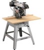
10 in. Stationary
RADIAL ARM SAW
Model No.
315.220100
Save
this
manual
for
future
reference.
CAUTION:
Read and
follow
all
Safety
Rules
and
Operating
Instructions
before
first
use of this
product.
Customer
Help
Line:
1-800-932-3188
•
Safety
•
Features
•
Assembly
•
Operation
•
Maintenance
• Parts List
Sears,
Roebuck
and
Co.,
3333
Beverly
Rd.,
Hoffman
Estates,
IL 60179
USA
Visit the Craftsman
web
page:
www.sears.com/craftsman
983000-041
5-02