Craftsman #10402 Operation Manual - Page 31
Leveung, The Table, Supports
 |
View all Craftsman #10402 manuals
Add to My Manuals
Save this manual to your list of manuals |
Page 31 highlights
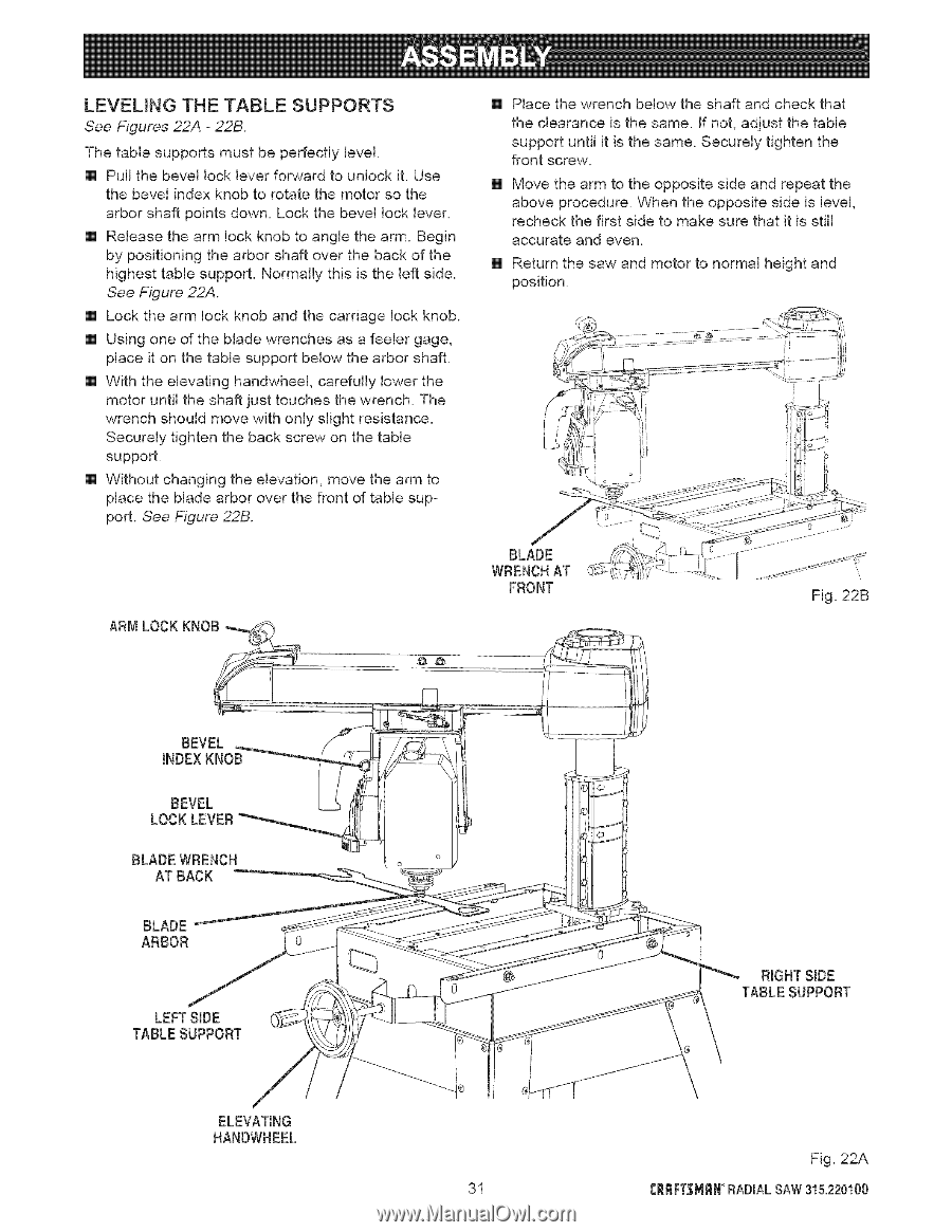
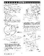
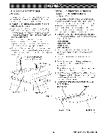
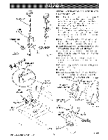
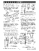
LEVEUNG THE TABLE SUPPORTS See Figures 22A - 22B. The table supports must be perfectly level. [] Pull the bevel lock lever forward to unlock it. Use the bevel index knob to rotate the motor so the arbor shaft points down. Lock the bevel lock lever. [] Release the arm lock knob to angle the arm. Begin by positioning the arbor shaft over the back of the highest table support. Normally this is the left side. See Figure 22A. [] Lock the arm lock knob and the carriage lock knob. [] Using one of the blade wrenches as a feeler gage, place it on the table support below the arbor shaft. [] With the elevating handwheel, carefully lower the motor until the shaft just touches the wrench. The wrench should move with only slight resistance. Securely tighten the back screw on the table support. [] Without changing the elevation, move the arm to place the blade arbor over the front of table support. See Figure 22B. ARM LOCK KNOB [] Place the wrench below the shaft and check that the clearance is the same. If not, adjust the table support until it is the same. Securely tighten the front screw. [] Move the arm to the opposite side and repeat the above procedure. When the opposite side is level, recheck the first side to make sure that it is still accurate and even. [] Return the saw and motor to normal height and position. BLADE WRENCHAT FRONT Fig. 22B BEVEL INDEXKNOB BEVEL LOCKLEVER BLADE WRENCH AT BACK BLADE ARBOR LEFT SIDE TABLE SUPPORT ELEVATING NANDWHEEL @_ RIGHTSIDE TABLE SUPPORT Fig. 22A 31 CRRFT'SMn°RNADIALSAW315.220100
-
 1
1 -
2
-
3
-
4
-
5
-
6
-
7
-
8
-
9
-
10
-
11
-
12
-
13
-
14
-
15
-
16
-
17
-
18
-
19
-
20
-
21
-
22
-
23
-
24
-
25
-
 26
26 -
 27
27 -
 28
28 -
 29
29 -
 30
30 -
 31
31 -
 32
32 -
 33
33 -
 34
34 -
 35
35 -
 36
36 -
37
-
38
-
39
-
40
-
41
-
42
-
43
-
44
-
45
-
46
-
47
-
48
-
49
-
50
-
51
-
52
-
53
-
54
-
55
-
56
-
57
-
58
-
59
-
60
-
61
-
62
-
63
-
64
-
65
-
66
-
67
-
68
-
69
-
70
-
71
-
72
-
73
-
74
-
75
-
76
-
77
-
78
-
79
-
80
-
81
-
82
-
83
-
84
-
85
-
86
 |
 |