Craftsman #10402 Operation Manual - Page 19
See s, 9A - 9D., See D., See s 9A and 9B., B., See B.,
 |
View all Craftsman #10402 manuals
Add to My Manuals
Save this manual to your list of manuals |
Page 19 highlights
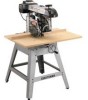
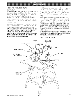
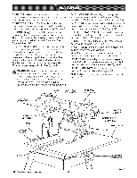
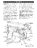
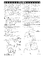
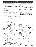
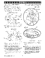
FEATURES LiST See Figures 9A - 9D. ADJUSTABLE TABLES - A narrow spacer table and wider rear table that can be repositioned or even replaced with different tables. See Figure 9C. ANTI-KICKBACK PAWLS - Toothed pawls that snag the work in case of kickback during rip cuts. (When the blade is parallel to the arm, the pawls are in front of the blade.) Keep the pawls in place to reduce risk of injury. See Figure 9D. ARM - The assembly extending from the column, which supports the yoke, the motor, and the blade. See Figure 9A. ARM LOCK KNOB - Controls arm angle. Use to set the arm to the positive stops at 0 °, 45 ° left, and 45 ° right and to lock the arm in place. Located on top of arm at front. See Figures 9A and 9B. BEVEL INDEX KNOB - Controls the blade angle between positive stops at 0°, 45 °, and 90 °. Located behind the handle. See Figure 9B. BEVEL INDEX SCALE - Shows the blade angle for bevel cuts and is located behind the handle. See Figure 9B. BEVEL LOCK LEVER - Sets and locks blade angle, it is located below the handle. See Figure 9B. BLADE - For maximum performance, use the Craftsman 40-tooth, 10 in. carbide-tipped blade provided with your saw. It is a high-quality combination blade suitable for ripping and crosscut operations. Blades recommended for other operations are listed in the Accessory section of this manual. The blade is powered by the main motor and turned off by the switch. See Figure 9D. WARNmNG: Use only blades rated for at least 5,000 rpm and recommended for use on this saw. Check with your nearest Sears retail store. BLADE GUARD ASSEMBLY - Protective unit over the blade, with a riving knife, anti-kickback pawls, an upper blade guard, a lower outer blade guard, and a lower inner blade guard. Always keep each item in place unless specifically instructed to move it. See Figures 9A and 9D. BLADE GUARD CLAMP SCREW - Secures the blade guard to the motor. Located between the blade and the motor. See Figure 9D. MITERSCALE ARM LOCK KNOB YOKE PIVOTLATCH YOKE RIP SCALE{S) COLUMNTUBE BEVEL INDEXKNOB BEVEL INDEXSCALE o __:__V i \° o BEVEL ER MOTOR 19 YOKE LOCKHANDLE COLUMNSUPPORT
-
 1
1 -
2
-
3
-
4
-
5
-
6
-
7
-
8
-
9
-
10
-
11
-
12
-
13
-
 14
14 -
 15
15 -
 16
16 -
 17
17 -
 18
18 -
 19
19 -
 20
20 -
 21
21 -
 22
22 -
 23
23 -
 24
24 -
25
-
26
-
27
-
28
-
29
-
30
-
31
-
32
-
33
-
34
-
35
-
36
-
37
-
38
-
39
-
40
-
41
-
42
-
43
-
44
-
45
-
46
-
47
-
48
-
49
-
50
-
51
-
52
-
53
-
54
-
55
-
56
-
57
-
58
-
59
-
60
-
61
-
62
-
63
-
64
-
65
-
66
-
67
-
68
-
69
-
70
-
71
-
72
-
73
-
74
-
75
-
76
-
77
-
78
-
79
-
80
-
81
-
82
-
83
-
84
-
85
-
86
 |
 |
