Craftsman #10402 Operation Manual - Page 32
Installing, Front, Table
 |
View all Craftsman #10402 manuals
Add to My Manuals
Save this manual to your list of manuals |
Page 32 highlights
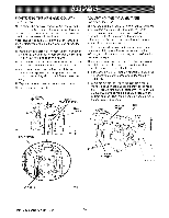
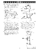
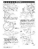
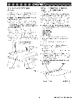
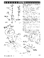
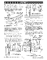
iNSTALLiNG THE FRONT TABLE See Figures 23A - 23C. Use this procedure to install the fixed front table. The top of the table has counterbored holes, predrifled from the top, around the center to attach the table, in the center are a counterbored hole and a small hole, which is not counterbored. They are used for raising or lowering the center of the table until it is level. [] Locate the front table and the following hardware: 1 tee nut 1 U-clip (1/4 in.) 1 setscrew (1/4-20 x 7/8 in.) 4 pan head screws (1/4-20 x 1 in.) 1 pan head screw (1/4-20 x 1-3/4 in.) 5 flat washers (5/8 in.) 4 lock washers (1/4 in.) 4 hex nuts (1/4-20) [] Place the front table on a solid worksurface, with the top surface face down. Place the tee nut in the non-counterbored hole and tap it in place with a hammer. SETSCREW _ SCREW _ / _'_ REAR OF U-CLIP ALIGN U-CLIP OVERTHiS HOLE SAW BASE Fig. 23B [] Place the long pan head screw into the center hole and thread into the U-clip. Do not tighten until the table has been checked for evenness. See Figure 23A. [] Place the setscrew through the small leveling hole and thread into the tee nut, but do not tighten. [] Put a 1 in. long pan head screw in the four remaining holes and through the holes in the support. Cap with a lock washer and hex nut. Tighten with a 7/16 in. wrench and phillips screwdriver. This completes installation of the front table. 1 in. _ SCREW SETSCREW 1-3/4 in. SCREW ZZ , !, ! FLAT WASHER REAR OF FRONTTABLE Fig. 23A [] Snap the U-clip onto the front edge of the saw base. Line up the hole in the U-cfip with the saw base hole just to the left of the center notch in saw base. See Figure 23B. [] Place the table, top up, on the table supports so the center counterbored hole lines up over the hole in the U-clip. [] Place a fiat washer in each counterbored hole. CRRF[_NRN RADIAL SAW 315.220100 32 LOCKWASNER HEX NUT Fig. 23C
-
 1
1 -
2
-
3
-
4
-
5
-
6
-
7
-
8
-
9
-
10
-
11
-
12
-
13
-
14
-
15
-
16
-
17
-
18
-
19
-
20
-
21
-
22
-
23
-
24
-
25
-
26
-
 27
27 -
 28
28 -
 29
29 -
 30
30 -
 31
31 -
 32
32 -
 33
33 -
 34
34 -
 35
35 -
 36
36 -
 37
37 -
38
-
39
-
40
-
41
-
42
-
43
-
44
-
45
-
46
-
47
-
48
-
49
-
50
-
51
-
52
-
53
-
54
-
55
-
56
-
57
-
58
-
59
-
60
-
61
-
62
-
63
-
64
-
65
-
66
-
67
-
68
-
69
-
70
-
71
-
72
-
73
-
74
-
75
-
76
-
77
-
78
-
79
-
80
-
81
-
82
-
83
-
84
-
85
-
86
 |
 |
