Craftsman #10402 Operation Manual - Page 33
Leveling, Front, Table, Jnstalung, Table, Spacer, Fence, Clamps
 |
View all Craftsman #10402 manuals
Add to My Manuals
Save this manual to your list of manuals |
Page 33 highlights
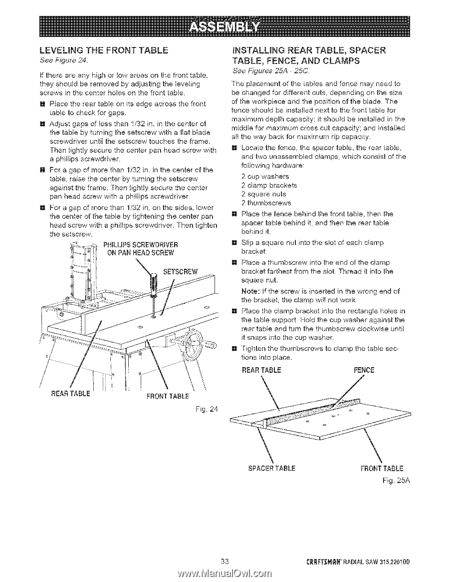
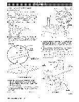
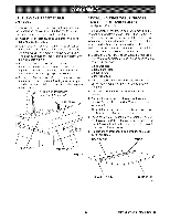
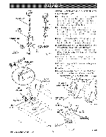
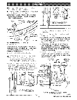
LEVELING THE FRONT TABLE See Figure 24. If there are any high or low areas on the front table, they should be removed by adjusting the leveling screws in the center holes on the front table. [] Place the rear table on its edge across the front table to check for gaps. [] Adjust gaps of Jess than 1/32 in. in the center of the table by turning the setscrew with a fiat blade screwdriver until the setscrew touches the frame. Then lightly secure the center pan head screw with a phiJJips screwdriver. [] For a gap of more than 1/32 in. in the center of the table, raise the center by turning the setscrew against the frame. Then lightly secure the center pan head screw with a phillips screwdriver. [] For a gap of more than 1/32 in. on the sides, lower the center of the table by tightening the center pan head screw with a phiJJips screwdriver. Then tighten the setscrew. PHILLIPSSCREWDRIVER ON PAN HEADSCREW SETSCREW JNSTALUNG REAR TABLE, SPACER TABLE, FENCE, AND CLAMPS See Figures 25A - 25C. The placement of the tables and fence may need to be changed for different cuts, depending on the size of the workpiece and the position of the blade. The fence should be installed next to the front table for maximum depth capacity; it should be installed in the middle for maximum cross cut capacity; and installed all the way back for maximum rip capacity. [] Locate the fence, the spacer table, the rear table, and two unassembied clamps, which consist of the following hardware: 2 cup washers 2 clamp brackets 2 square nuts 2 thumbscrews [] Place the fence behind the front table, then the spacer table behind it, and then the rear table behind it. [] Slip a square nut into the slot of each clamp bracket. [] Place a thumbscrew into the end of the clamp bracket farthest from the slot. Thread it into the square nut. Note: If the screw is inserted in the wrong end of the bracket, the clamp will not work. [] Place the clamp bracket into the rectangle holes in the table support. Hold the cup washer against the rear table and turn the thumbscrew clockwise until it snaps into the cup washer. [] Tighten the thumbscrews to clamp the table sections into place. REARTABLE FENCE REARTABLE FRONTTABLE Fig. 24 SPACERTABLE FRONTTABLE Fig. 25A 33 J:RRFTSM_J°NRADIAL SAW 315.220100
-
 1
1 -
2
-
3
-
4
-
5
-
6
-
7
-
8
-
9
-
10
-
11
-
12
-
13
-
14
-
15
-
16
-
17
-
18
-
19
-
20
-
21
-
22
-
23
-
24
-
25
-
26
-
27
-
 28
28 -
 29
29 -
 30
30 -
 31
31 -
 32
32 -
 33
33 -
 34
34 -
 35
35 -
 36
36 -
 37
37 -
 38
38 -
39
-
40
-
41
-
42
-
43
-
44
-
45
-
46
-
47
-
48
-
49
-
50
-
51
-
52
-
53
-
54
-
55
-
56
-
57
-
58
-
59
-
60
-
61
-
62
-
63
-
64
-
65
-
66
-
67
-
68
-
69
-
70
-
71
-
72
-
73
-
74
-
75
-
76
-
77
-
78
-
79
-
80
-
81
-
82
-
83
-
84
-
85
-
86
 |
 |