Craftsman #10402 Operation Manual - Page 39
Squaring, Blade, To Fence
 |
View all Craftsman #10402 manuals
Add to My Manuals
Save this manual to your list of manuals |
Page 39 highlights
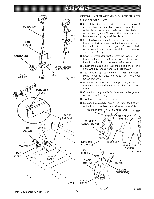
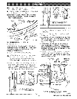
SQUARING BLADE TO FENCE See Figures 31A - 31C. This procedure squares the miter angle of the blade to the fence to reduce the risk of binding and kickback. If the blade is not square to the fence, the yoke assembly must be rotated slightly. Have a framing square, a 1/2 in. wrench, and a phillips screwdriver at hand. The blade should be lowered to just clear the table. Release the carriage lock knob. ,_ WARNING: The blade must be angled at 90 ° to the fence when the handle is at the front of the saw. If not, kickback could result during a cross cut. Kickback can cause serious injury by throwing the workpiece toward the operator. In addition, a faulty miter angle on the blade can splinter or burn the cut edges of the workpiece during cross cuts or rip cuts. • Use the arm lock knob to index and lock the arm in 0 ° miter position (straight forward). • Pull the yoke assembly forward to the front of the arm. Lock the carriage lock knob. • Place the short end of the framing square against the fence. Rotate the square to 45 ° to the table. Place the long edge across the flat surface of the blade, below the center of the blade. (Do not place the edge against a tooth.) • Check whether the blade is flat against the edge for the entire length or whether a gap is visible. • If the blade needs adjustment, remove the right side carriage cover with a phillips screwdriver. ARM LOCKKNOB • Release the yoke lock handle (below the yoke on the right). With a 1/2 in. wrench, slightly loosen the two hex bolts holding the yoke pivot latch. • Rotate yoke assembly until the gap is eliminated. • Lock the yoke lock handle. Retighten the two hex bolts on the yoke pivot latch. • Replace the carriage cover. • Loosen the carriage lock knob and guide the yoke assembly to the back of the arm. SAW VIEWED FROM ABOVE , NEEDED " BLADE _ _ADJUSTMENT NO ADJUSTMENTNEEDED FENCE FRAMING SQUARE BLADE GAP - ADJUSTMENTNEEDED Fig. 31B FENCE FRAMINGSQUARE Fig. 31A 39 HEX BOLTS YOKELOCKHANDLE Fig. 31C CRRFTSNR° HRADIAL SAW315.220100
-
 1
1 -
2
-
3
-
4
-
5
-
6
-
7
-
8
-
9
-
10
-
11
-
12
-
13
-
14
-
15
-
16
-
17
-
18
-
19
-
20
-
21
-
22
-
23
-
24
-
25
-
26
-
27
-
28
-
29
-
30
-
31
-
32
-
33
-
 34
34 -
 35
35 -
 36
36 -
 37
37 -
 38
38 -
 39
39 -
 40
40 -
 41
41 -
 42
42 -
 43
43 -
 44
44 -
45
-
46
-
47
-
48
-
49
-
50
-
51
-
52
-
53
-
54
-
55
-
56
-
57
-
58
-
59
-
60
-
61
-
62
-
63
-
64
-
65
-
66
-
67
-
68
-
69
-
70
-
71
-
72
-
73
-
74
-
75
-
76
-
77
-
78
-
79
-
80
-
81
-
82
-
83
-
84
-
85
-
86
 |
 |
