Craftsman #10402 Operation Manual - Page 24
ARMcAP
 |
View all Craftsman #10402 manuals
Add to My Manuals
Save this manual to your list of manuals |
Page 24 highlights
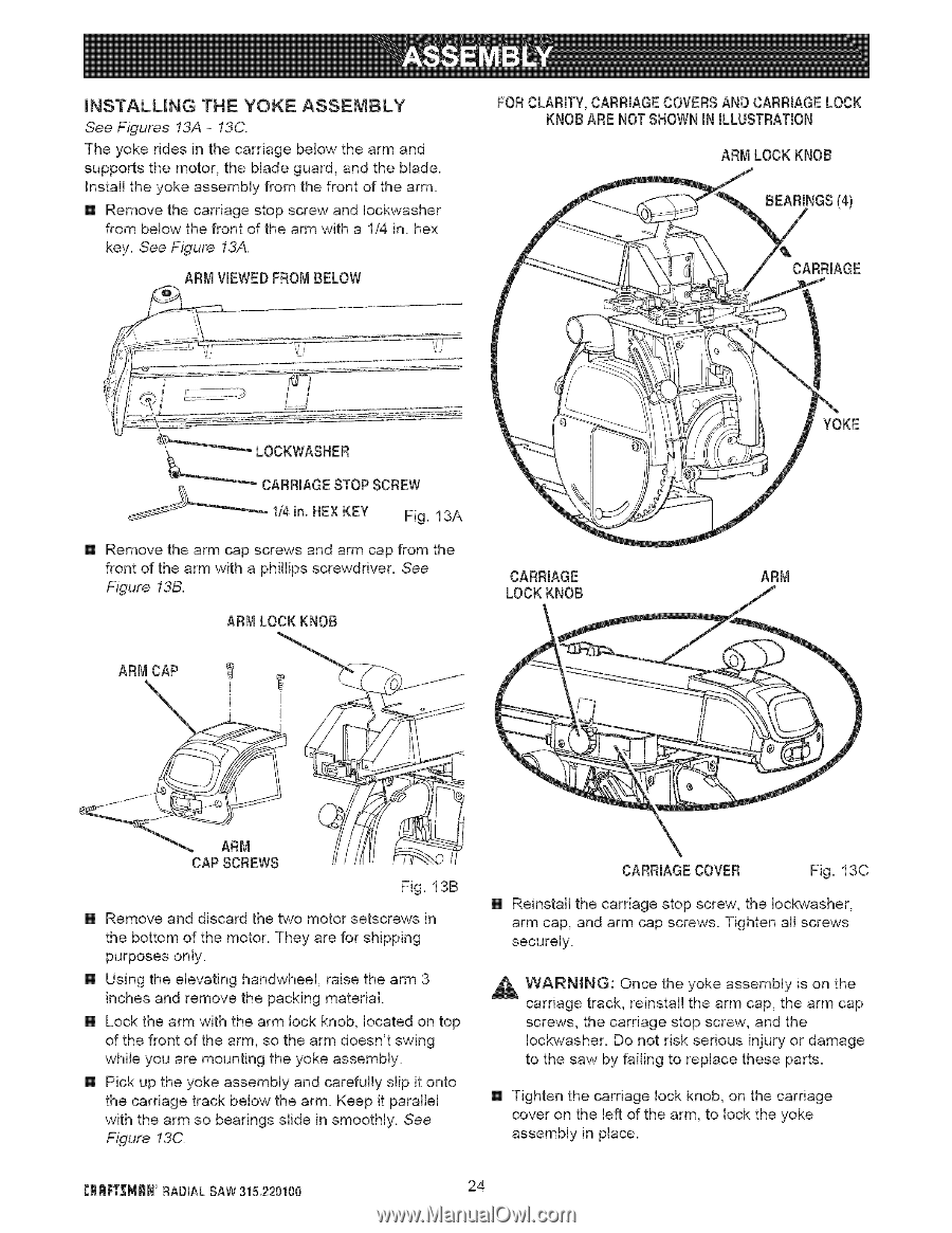
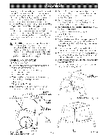
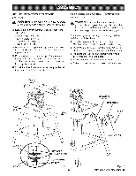
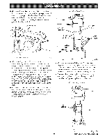
INSTALUNG THE YOKE ASSEMBLY See Figures 13A- 13C. The yoke rides in the carriage below the arm and supports the motor, the blade guard, and the blade. Install the yoke assembly from the front of the arm. [] Remove the carriage stop screw and lockwasher from below the front of the arm with a 1/4 in. hex key. See Figure 13A. ARM VIEWEDFROMBELOW FOR CLARITY,CARRIAGECOVERSAND CARRIAGELOCK KNOBARE NOT SHOWNIN ILLUSTRATION ARM LOCK KNOB BEARINGS(4) CARRIAGE LOCKWASHER __CARRIAGE STOPSCREW 1/4in. HEXKEY Fig. 13A [] Remove the arm cap screws and arm cap from the front of the arm with a phillips screwdriver. See Figure 13B. ARM LOCKKNOB ARMcAP ' I CARRIAGE LOCKKNOB i ! YOKE ARM Fig. 13B [] Remove and discard the two motor setscrews in the bottom of the motor. They are for shipping purposes only. [] Using the elevating handwheel, raise the arm 3 inches and remove the packing material. [] Lock the arm with the arm lock knob, located on top of the front of the arm, so the arm doesn't swing while you are mounting the yoke assembly. [] Pick up the yoke assembly and carefully slip it onto the carriage track below the arm. Keep it parallel with the arm so bearings slide in smoothly. See F_gure !3C. CARRIAGECOVER Fig. 13C Reinstall the carriage stop screw, the Iockwasher, arm cap, and arm cap screws. Tighten all screws securely. _ WARMNG: Once the yoke assembly is on the carriage track, reinstall the arm cap, the arm cap screws, the carriage stop screw, and the lockwasher. Do not risk serious injury or damage to the saw by failing to replace these parts. [] Tighten the carriage lock knob, on the carriage cover on the left of the arm, to lock the yoke assembly in place. CRRF[_MRN RADIAL SAW 315.220100 24
-
 1
1 -
2
-
3
-
4
-
5
-
6
-
7
-
8
-
9
-
10
-
11
-
12
-
13
-
14
-
15
-
16
-
17
-
18
-
 19
19 -
 20
20 -
 21
21 -
 22
22 -
 23
23 -
 24
24 -
 25
25 -
 26
26 -
 27
27 -
 28
28 -
 29
29 -
30
-
31
-
32
-
33
-
34
-
35
-
36
-
37
-
38
-
39
-
40
-
41
-
42
-
43
-
44
-
45
-
46
-
47
-
48
-
49
-
50
-
51
-
52
-
53
-
54
-
55
-
56
-
57
-
58
-
59
-
60
-
61
-
62
-
63
-
64
-
65
-
66
-
67
-
68
-
69
-
70
-
71
-
72
-
73
-
74
-
75
-
76
-
77
-
78
-
79
-
80
-
81
-
82
-
83
-
84
-
85
-
86
 |
 |