Craftsman #10402 Operation Manual - Page 27
Setting, Bevel, Lever
 |
View all Craftsman #10402 manuals
Add to My Manuals
Save this manual to your list of manuals |
Page 27 highlights
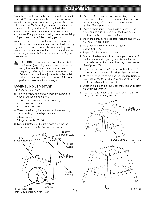
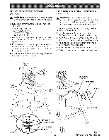
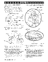
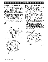
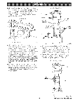
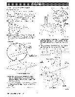
SETTING THE BEVEL LOCK LEVER See Figures 18A- 18C. The bevel lock lever locks the blade at desired angles other than the preset positive stop angles. The bevel lock lever is preset at the factory but may need readjustment after shipping or extended use. Check for overtightness or looseness and make any necessary adjustments as follows: The bevel lock lever is located on the front of the yoke assembly, near the bottom. It is attached to a clamp bolt that controls the amount of tightness. [] Pull the bevel lock lever forward to unlock it. Use the bevel index knob (just under the handle) to rotate the motor approximately 30 °. Lock the bevel lock lever. [] if the bevel lock lever is difficult to lock, the clamp bolt needs to be loosened. If the motor can be forced out of position, the clamp bolt needs to be tightened. [] Remove the socket screw (under the bevel lock lever) and star washer with a 1/8 in. hex key. [] Use the bevel lock handle as a wrench to tighten or loosen the clamp bolt. The clamp bolt has a righthanded thread. Tighten it left to right. [] When the bolt is correctly set, remove the bevel lock lever from the clamp bolt and place it roughly parallel to the yoke assembly. [] Replace the socket screw and star washer. Recheck the tightness of the bevel lock lever. Repeat the steps above until the motor is secure when locked, and the bevel lock lever fits squarely against the yoke assembly. CLAMP BOLT m 1/8 in. BEX KEY ./_ I BEVEL LOCKLEVER Fig. 18B / BEVEL LOCK LEVERiN CORRECTLOCKEDPOSITION Fig. 18C BEVEL LOCBKEVLEEVL ER INDEXKNOB MOTOR Fig. 18A 27 t:RRFTSMnN RADIAL SAW 315.220100
-
 1
1 -
2
-
3
-
4
-
5
-
6
-
7
-
8
-
9
-
10
-
11
-
12
-
13
-
14
-
15
-
16
-
17
-
18
-
19
-
20
-
21
-
 22
22 -
 23
23 -
 24
24 -
 25
25 -
 26
26 -
 27
27 -
 28
28 -
 29
29 -
 30
30 -
 31
31 -
 32
32 -
33
-
34
-
35
-
36
-
37
-
38
-
39
-
40
-
41
-
42
-
43
-
44
-
45
-
46
-
47
-
48
-
49
-
50
-
51
-
52
-
53
-
54
-
55
-
56
-
57
-
58
-
59
-
60
-
61
-
62
-
63
-
64
-
65
-
66
-
67
-
68
-
69
-
70
-
71
-
72
-
73
-
74
-
75
-
76
-
77
-
78
-
79
-
80
-
81
-
82
-
83
-
84
-
85
-
86
 |
 |
