Craftsman #10402 Operation Manual - Page 36
Nstalling, Rip Scale, Nd_cators
 |
View all Craftsman #10402 manuals
Add to My Manuals
Save this manual to your list of manuals |
Page 36 highlights
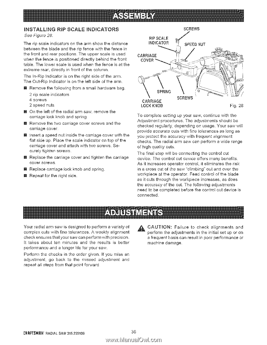
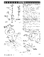
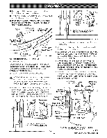
_NSTALLING RiP SCALE _ND_CATORS See Figure 28. The rip scale indicators on the arm show the distance between the blade and the rip fence with the fence in the front and rear positions. The upper scale is used when the fence is positioned directly behind the front table. The lower scale is used when the fence is at the extreme rear, directly in front of the column. The In-Rip Indicator is on the right side of the arm. The Out-Rip indicator is on the left side of the arm. [] Remove the following from a small hardware bag. 2 rip scale indicators 4 screws 2 speed nuts [] On the left of the radial arm saw, remove the carriage lock knob and spring. [] Remove the two carriage cover screws and the carriage cover. [] insert a speed nut inside the carriage cover with the flat side up. Place the scale indicator on top of the carriage cover and attach with two screws. Securely tighten screws. [] Replace the carriage cover and tighten the carriage cover screws. [] Replace carriage lock knob and spring. [] Repeat for the right side. RIP SCALE INDICATOR CARRIAGE SCREWS SPEEDNUT SPRING CARRIAGE LOCK KNOB SCREWS Fig. 28 To complete setting up your saw, continue with the Adjustment procedures. The adjustments should be checked regularly, depending on usage. Your saw will provide accurate cuts with fine tolerances as long as you protect the accuracy with frequent alignment checks. The radial arm saw can perform a wide range of high quality cuts. The final step will be connecting the control cut device. The control cut device offers many benefits. As it increases operator control, it eliminates the risk in a cross cut of the saw "climbing" out and over the workpiece at the operator. Feed control of the blade as it cuts through the workpiece increases, as does the accuracy of the cut. The following adjustments need to be completed before the control cut device is connected. Your radial arm saw is designed to perform a variety of complex cuts with fine tolerances. A weekly alignment check ensures that your saw can perform with precision. It takes about ten minutes and the results is better performance and a longer life for your saw. Perform the checks in the order given. If you miss an adjustment, go back to the missed adjustment and repeat all steps from that point forward. _ CAUTmON: Failure to check alignments and perform the adjustments in the initial set up or on a frequent basis can result in poor performance or machine damage. CRRF[_MRN RADIAL SAW 315.220100 36
-
 1
1 -
2
-
3
-
4
-
5
-
6
-
7
-
8
-
9
-
10
-
11
-
12
-
13
-
14
-
15
-
16
-
17
-
18
-
19
-
20
-
21
-
22
-
23
-
24
-
25
-
26
-
27
-
28
-
29
-
30
-
 31
31 -
 32
32 -
 33
33 -
 34
34 -
 35
35 -
 36
36 -
 37
37 -
 38
38 -
 39
39 -
 40
40 -
 41
41 -
42
-
43
-
44
-
45
-
46
-
47
-
48
-
49
-
50
-
51
-
52
-
53
-
54
-
55
-
56
-
57
-
58
-
59
-
60
-
61
-
62
-
63
-
64
-
65
-
66
-
67
-
68
-
69
-
70
-
71
-
72
-
73
-
74
-
75
-
76
-
77
-
78
-
79
-
80
-
81
-
82
-
83
-
84
-
85
-
86
 |
 |