Craftsman #10402 Operation Manual - Page 21
See B., See D., See See s, 9A and 9C.,
 |
View all Craftsman #10402 manuals
Add to My Manuals
Save this manual to your list of manuals |
Page 21 highlights
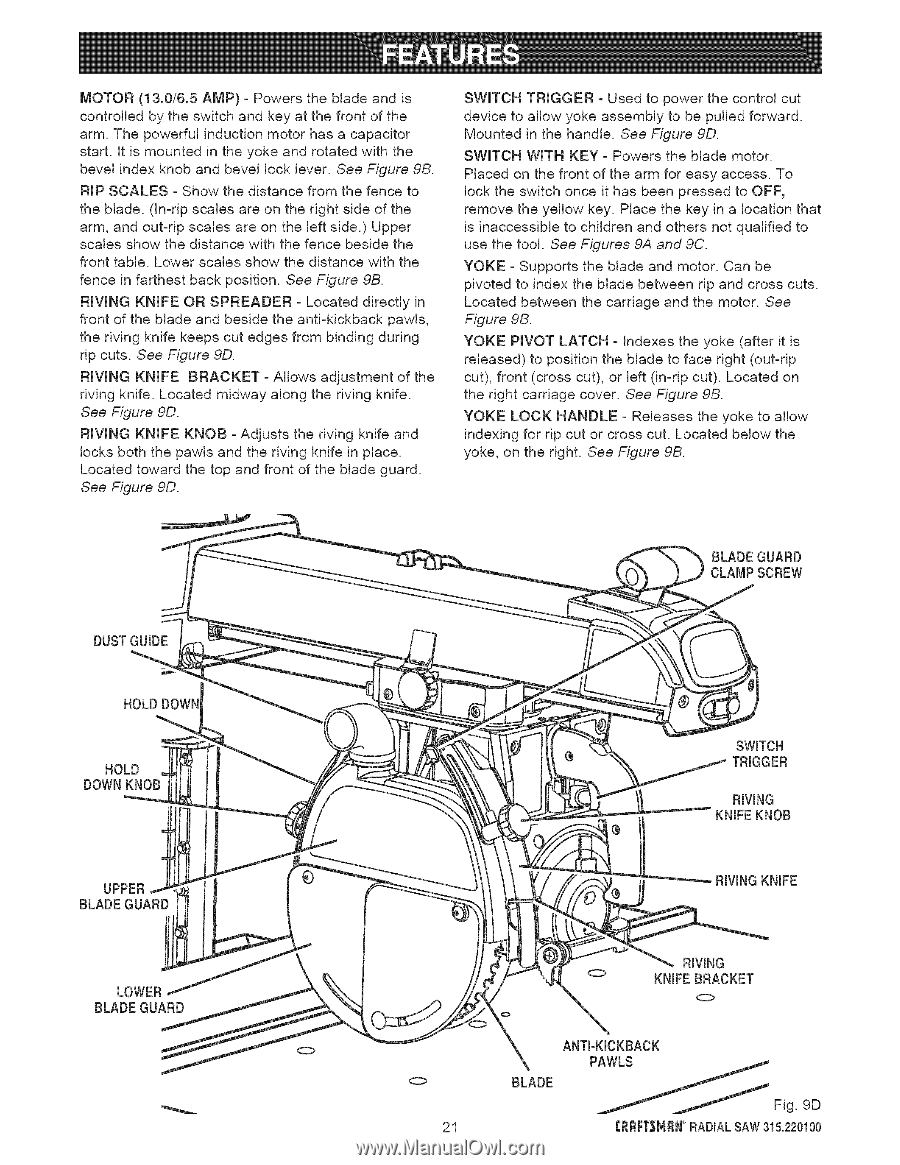
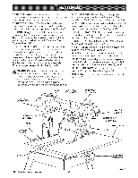
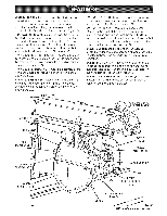
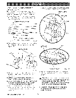
MOTOR (13.0/6.5 AMP) - Powers the blade and is controlled by the switch and key at the front of the arm. The powerful induction motor has a capacitor start, it is mounted in the yoke and rotated with the bevel index knob and bevel lock lever. See Figure 9B. RIP SCALES - Show the distance from the fence to the blade. (In-rip scales are on the right side of the arm, and out-rip scales are on the left side.) Upper scales show the distance with the fence beside the front table. Lower scales show the distance with the fence in farthest back position. See Figure 9B. RIVING KNIFE OR SPREADER - Located directly in front of the blade and beside the anti-kickback pawls, the riving knife keeps cut edges from binding during rip cuts. See Figure 9D. RIVING KNIFE BRACKET - Allows adjustment of the riving knife. Located midway along the riving knife. See Figure 9D. RIVING KNIFE KNOB - Adjusts the riving knife and locks both the pawls and the riving knife in place. Located toward the top and front of the blade guard. See Figure 9D. SWITCH TRIGGER - Used to power the control cut device to allow yoke assembly to be pulled forward. Mounted in the handle. See Figure 9D. SWITCH WITH KEY - Powers the blade motor. Placed on the front of the arm for easy access. To lock the switch once it has been pressed to OFF, remove the yellow key. Place the key in a location that is inaccessible to children and others not qualified to use the tool. See Figures 9A and 9C. YOKE - Supports the blade and motor. Can be pivoted to index the blade between rip and cross cuts. Located between the carriage and the motor. See Figure 9B. YOKE PIVOT LATCH - Indexes the yoke (after it is released) to position the blade to face right (out-rip cut), front (cross cut), or left (in-rip cut). Located on the right carriage cover. See Figure 9B. YOKE LOCK HANDLE - Releases the yoke to allow indexing for rip cut or cross cut. Located below the yoke, on the right. See Figure 9B. BLADE GUARD CLAMP SCREW DUSTGUIDE HOLD DOWN HOLD DOWN KNOB UPPER BLADE GUARD LOWER BLADEGUARD SWITCH TRIGGER RIVING KNIFEKNOB RIVINGKNIFE RIVING KNIFE BRACKET 0 BLADE 21
-
 1
1 -
2
-
3
-
4
-
5
-
6
-
7
-
8
-
9
-
10
-
11
-
12
-
13
-
14
-
15
-
 16
16 -
 17
17 -
 18
18 -
 19
19 -
 20
20 -
 21
21 -
 22
22 -
 23
23 -
 24
24 -
 25
25 -
 26
26 -
27
-
28
-
29
-
30
-
31
-
32
-
33
-
34
-
35
-
36
-
37
-
38
-
39
-
40
-
41
-
42
-
43
-
44
-
45
-
46
-
47
-
48
-
49
-
50
-
51
-
52
-
53
-
54
-
55
-
56
-
57
-
58
-
59
-
60
-
61
-
62
-
63
-
64
-
65
-
66
-
67
-
68
-
69
-
70
-
71
-
72
-
73
-
74
-
75
-
76
-
77
-
78
-
79
-
80
-
81
-
82
-
83
-
84
-
85
-
86
 |
 |