D-Link DES-3526DC Product Manual - Page 190
Config Firmware Image, Ping Test
 |
View all D-Link DES-3526DC manuals
Add to My Manuals
Save this manual to your list of manuals |
Page 190 highlights
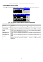
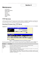
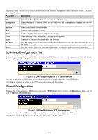
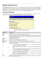
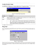
xStack DES-3500 Series Layer 2 Stackable Fast Ethernet Managed Switch User Manual Config Firmware Image The Config Firmware Image window allows users to configure firmware images saved in the memory of the Switch. To access the following window, click Maintenance > MULTIPLE IMAGE Services > Config Firmware Image. Figure 9- 6. Config Firmware Image window This window offers the following information: Parameter Description Image Action Select the firmware image to be configured using the pull-down menu. The Switch allows two firmware images to be stored in the Switch's memory. This field has two options for configuration. • Delete - Select this option to delete the firmware image specified in the Image field above. • Boot - Select this option to set the firmware image specified above as the boot up firmware for the Switch. This firmware will be set as the boot up firmware after a switch reboot has been performed. The default setting has firmware image ID 1 as the boot up firmware image for the Switch unless specified here. Click Apply to implement changes made. Ping Test Ping is a small program that sends ICMP Echo packets to the IP address you specify. The destination node then responds to or "echoes" the packets sent from the Switch. This is very useful to verify connectivity between the Switch and other nodes on the network. Figure 9- 7. Ping Test window The user may use Infinite times radio button, in the Repeat Pinging for field, which will tell the ping program to keep sending ICMP Echo packets to the specified IP address until the program is stopped. The user may opt to choose a specific number of times to ping the Target IP Address by clicking its radio button and entering a number between 1 and 255. Click Start to initiate the Ping program. 176
-
 1
1 -
2
-
3
-
4
-
5
-
6
-
7
-
8
-
9
-
10
-
11
-
12
-
13
-
14
-
15
-
16
-
17
-
18
-
19
-
20
-
21
-
22
-
23
-
24
-
25
-
26
-
27
-
28
-
29
-
30
-
31
-
32
-
33
-
34
-
35
-
36
-
37
-
38
-
39
-
40
-
41
-
42
-
43
-
44
-
45
-
46
-
47
-
48
-
49
-
50
-
51
-
52
-
53
-
54
-
55
-
56
-
57
-
58
-
59
-
60
-
61
-
62
-
63
-
64
-
65
-
66
-
67
-
68
-
69
-
70
-
71
-
72
-
73
-
74
-
75
-
76
-
77
-
78
-
79
-
80
-
81
-
82
-
83
-
84
-
85
-
86
-
87
-
88
-
89
-
90
-
91
-
92
-
93
-
94
-
95
-
96
-
97
-
98
-
99
-
100
-
101
-
102
-
103
-
104
-
105
-
106
-
107
-
108
-
109
-
110
-
111
-
112
-
113
-
114
-
115
-
116
-
117
-
118
-
119
-
120
-
121
-
122
-
123
-
124
-
125
-
126
-
127
-
128
-
129
-
130
-
131
-
132
-
133
-
134
-
135
-
136
-
137
-
138
-
139
-
140
-
141
-
142
-
143
-
144
-
145
-
146
-
147
-
148
-
149
-
150
-
151
-
152
-
153
-
154
-
155
-
156
-
157
-
158
-
159
-
160
-
161
-
162
-
163
-
164
-
165
-
166
-
167
-
168
-
169
-
170
-
171
-
172
-
173
-
174
-
175
-
176
-
177
-
178
-
179
-
180
-
181
-
182
-
183
-
184
-
 185
185 -
 186
186 -
 187
187 -
 188
188 -
 189
189 -
 190
190 -
 191
191 -
 192
192 -
 193
193 -
 194
194 -
 195
195 -
196
-
197
-
198
-
199
-
200
-
201
-
202
-
203
-
204
-
205
-
206
-
207
-
208
-
209
-
210
-
211
-
212
-
213
-
214
-
215
-
216
-
217
-
218
-
219
-
220
-
221
-
222
-
223
-
224
-
225
-
226
-
227
-
228
-
229
-
230
-
231
-
232
-
233
-
234
-
235
-
236
-
237
-
238
-
239
-
240
-
241
-
242
-
243
-
244
-
245
-
246
-
247
-
248
-
249
-
250
-
251
-
252
-
253
-
254
-
255
-
256
-
257
-
258
-
259
-
260
 |
 |
