Dell Inspiron 14 5410 2-in-1 Service Manual
Dell Inspiron 14 5410 2-in-1 Manual
 |
View all Dell Inspiron 14 5410 2-in-1 manuals
Add to My Manuals
Save this manual to your list of manuals |
Dell Inspiron 14 5410 2-in-1 manual content summary:
- Dell Inspiron 14 5410 2-in-1 | Service Manual - Page 1
Inspiron 14 5410 2-in-1 Service Manual Regulatory Model: P147G Regulatory Type: P147G002 March 2021 Rev. A00 - Dell Inspiron 14 5410 2-in-1 | Service Manual - Page 2
use of your product. CAUTION: A CAUTION indicates either potential damage to hardware or loss of data and tells you how to avoid the problem. WARNING: A WARNING indicates a potential for property damage, personal injury, or death. © 2021 Dell Inc. or its subsidiaries. All rights reserved. Dell, EMC - Dell Inspiron 14 5410 2-in-1 | Service Manual - Page 3
6 Before working inside your computer...6 Safety instructions...6 Electrostatic discharge-ESD protection...7 ESD field service kit ...7 Transporting sensitive components...8 Entering Service Mode...8 After working inside your computer...9 Exiting Service Mode...9 Chapter 2: Removing and installing - Dell Inspiron 14 5410 2-in-1 | Service Manual - Page 4
setup password 73 Clearing CMOS settings...73 Clearing BIOS (System Setup) and System passwords 74 Chapter 5: Troubleshooting...75 SupportAssist diagnostics...75 Locate the Service Tag or Express Service Code of your Dell computer 75 System diagnostic lights...75 Built-in self-test (BIST)...76 - Dell Inspiron 14 5410 2-in-1 | Service Manual - Page 5
Flashing the BIOS...77 Flashing BIOS (USB key)...78 Backup media and recovery options...78 WiFi power cycle...78 Drain residual flea power (perform hard reset)...78 Chapter 6: Getting help and contacting Dell 80 Contents 5 - Dell Inspiron 14 5410 2-in-1 | Service Manual - Page 6
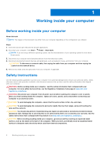
and the contacts. CAUTION: You should only perform troubleshooting and repairs as authorized or directed by the Dell technical assistance team. Damage due to servicing that is not authorized by Dell is not covered by your warranty. See the safety instructions that is shipped with the product or at - Dell Inspiron 14 5410 2-in-1 | Service Manual - Page 7
may not be obvious, such as intermittent problems or a shortened product life span. As The more difficult type of damage to recognize and troubleshoot is the intermittent (also called latent or " on the system being worked on. Once deployed properly, service parts can be removed from the ESD bag and - Dell Inspiron 14 5410 2-in-1 | Service Manual - Page 8
kit, it is a best practice to regularly test the strap prior to each service call, and at a minimum, test once per week. A wrist strap stable base, and point your toes out. 2. Tighten stomach muscles. Abdominal muscles support your spine when you lift, offsetting the force of the load. 3. Lift with - Dell Inspiron 14 5410 2-in-1 | Service Manual - Page 9
prompting you to remove the AC adapter appears on the screen. Remove the AC adapter and then press any key to continue the Service Mode procedure. NOTE: The Service Mode procedure automatically skips the following step if the Owner Tag of the computer is not set up in advance by the manufacturer - Dell Inspiron 14 5410 2-in-1 | Service Manual - Page 10
2 Removing and installing components NOTE: The images in this document may differ from your computer depending on the configuration you ordered. Recommended tools The procedures in this document may require the following tools: ● Phillips screwdrivers #0 ● Plastic scribe Screw list NOTE: When - Dell Inspiron 14 5410 2-in-1 | Service Manual - Page 11
Table 1. Screw list Component Secured to Screw type I/O board Palm-rest and keyboard M2x3 assembly Display hinges Palm-rest and keyboard M2.5x3.5 assembly Power-button with optional fingerprint reader Palm-rest and keyboard M1.6X2 assembly Power-adapter port Palm-rest and keyboard 2x3 - Dell Inspiron 14 5410 2-in-1 | Service Manual - Page 12
1. Base cover 2. Power button with optional fingerprint reader 3. Memory modules 4. USB Type-C bracket 5. Heat sink 6. I/O-board cable 7. System board 8. Touchpad cable 9. Battery 10. Speakers 11. Touchpad 12. Touchpad-bracket 13. Display assembly 14. Palm-rest and keyboard assembly 15. Solid-state - Dell Inspiron 14 5410 2-in-1 | Service Manual - Page 13
representative for purchase options. Base cover Removing the base cover Prerequisites 1. Follow the procedure in Before working inside your computer. 2. Enter Service Mode. About this task The following images indicate the location of the base cover and provide a visual representation of the removal - Dell Inspiron 14 5410 2-in-1 | Service Manual - Page 14
Steps 1. Remove the four screws (M2x4) that secure the base cover to the palm-rest and keyboard assembly. 2. Loosen the three captive screws that secure the base cover to the palm-rest and keyboard assembly. NOTE: Upon loosening the three captive screws, the base cover will open up creating a gap - Dell Inspiron 14 5410 2-in-1 | Service Manual - Page 15
palm-rest and keyboard assembly. 3. Tighten the three captive screws that secure the base cover to the palm-rest and keyboard assembly. Next steps 1. Exit Service Mode. 2. Follow the procedure in After working inside your computer. Removing and installing components 15 - Dell Inspiron 14 5410 2-in-1 | Service Manual - Page 16
kind to pry on or against the battery. ● Ensure any screws during the servicing of this product are not lost or misplaced, to prevent accidental puncture or damage can be dangerous. In such an instance, contact Dell technical support for assistance. See www.dell.com/contactdell. ● Always purchase - Dell Inspiron 14 5410 2-in-1 | Service Manual - Page 17
Steps 1. Peel the tape that secures the battery cable to the system board (applicable only if not peeled earlier). 2. Disconnect the battery cable from the system board (applicable only if not disconnected earlier). 3. Remove the three screws (M2x3) that secure the battery to the palm-rest and - Dell Inspiron 14 5410 2-in-1 | Service Manual - Page 18
Steps 1. Peel the tape that secures the battery cable to the system board (applicable only if not peeled earlier). 2. Disconnect the battery cable from the system board (applicable only if not disconnected earlier). 3. Remove the five screws (M2x3) that secure the battery to the palm-rest and - Dell Inspiron 14 5410 2-in-1 | Service Manual - Page 19
Steps 1. Using the alignment posts, place the battery on the palm-rest and keyboard assembly. 2. Replace the three screws (M2x3) that secure the battery to the palm-rest and keyboard assembly. 3. Connect the battery cable to the system board. 4. Adhere the tape that secures the battery cable to the - Dell Inspiron 14 5410 2-in-1 | Service Manual - Page 20
your computer. Coin-cell battery Removing the coin-cell battery Prerequisites 1. Follow the procedure in Before working inside your computer. 2. Enter Service Mode. NOTE: Removing the I/O-board cable is equivalent to removing the coin-cell battery. It resets the BIOS setup program's settings to - Dell Inspiron 14 5410 2-in-1 | Service Manual - Page 21
Steps 1. Disconnect the coin-cell battery from the I/O board. 2. Peel the coin-cell battery and lift it off the slot on the palm-rest and keyboard assembly. Installing the coin-cell battery Prerequisites If you are replacing a component, remove the existing component before performing the - Dell Inspiron 14 5410 2-in-1 | Service Manual - Page 22
the coin-cell battery cable to the I/O board. Next steps 1. Install the base cover. 2. Follow the procedure in After working inside your computer. 3. Exit Service Mode. Memory module Removing the memory module Prerequisites 1. Follow the procedure in Before working inside your computer. 2. Enter - Dell Inspiron 14 5410 2-in-1 | Service Manual - Page 23
Steps 1. Lift the flap to access the memory module. 2. Use your fingertips to carefully spread apart the securing-clips on each end of the memory-module slot until the memory module pops up. 3. Slide and remove the memory module from the memory-module slot. NOTE: Repeat step 2 to step 3 to remove - Dell Inspiron 14 5410 2-in-1 | Service Manual - Page 24
4 to install any other memory modules in your computer. Next steps 1. Install the base cover. 2. Follow the procedure in After working inside your computer. 3. Exit Service Mode. 24 Removing and installing components - Dell Inspiron 14 5410 2-in-1 | Service Manual - Page 25
Wireless card Removing the wireless card Prerequisites 1. Follow the procedure in Before working inside your computer. 2. Enter Service Mode. 3. Remove the base cover. About this task The following image indicates the location of the wireless card and provides a visual representation of the removal - Dell Inspiron 14 5410 2-in-1 | Service Manual - Page 26
the antenna cables to the wireless card. The following table provides the antenna-cable color scheme for the wireless card that is supported by your computer. Table 2. Antenna-cable color scheme Connectors on the wireless card Main Antenna-cable color Silkscreen marking White MAIN △ (white - Dell Inspiron 14 5410 2-in-1 | Service Manual - Page 27
to the wireless-card bracket. Next steps 1. Install the base cover. 2. Follow the procedure in After working inside your computer. 3. Exit Service Mode. Solid-state drive Removing the M.2 2280 solid-state drive Prerequisites 1. Follow the procedure in Before working inside your computer. 2. Enter - Dell Inspiron 14 5410 2-in-1 | Service Manual - Page 28
drive Prerequisites If you are replacing a component, remove the existing component before performing the installation procedure. About this task This computer supports two solid-state drive form factors. ● M.2 2230 ● M.2 2280 If you are replacing the M.2 2280 solid-state drive with an M.2 2230 - Dell Inspiron 14 5410 2-in-1 | Service Manual - Page 29
The following image indicates the location of the M.2 2280 solid-state drive and provides a visual representation of the installation procedure. NOTE: Perform step 1 to step 4 if you are replacing the M.2 2230 solid-state drive with an M.2 2280 solid-state drive. Removing and installing components - Dell Inspiron 14 5410 2-in-1 | Service Manual - Page 30
8. Adhere the tape that secures the antenna calbe to the palm-rest and solid-state drive. Next steps 1. Install the base cover. 2. Exit Service Mode. 3. Follow the procedure in After working inside your computer. Removing the M.2 2230 solid-state drive Prerequisites 1. Follow the procedure in Before - Dell Inspiron 14 5410 2-in-1 | Service Manual - Page 31
drive Prerequisites If you are replacing a component, remove the existing component before performing the installation procedure. About this task This computer supports two solid-state drive form factors. ● M.2 2230 ● M.2 2280 If you are replacing the M.2 2230 solid-state drive with an M.2 2280 - Dell Inspiron 14 5410 2-in-1 | Service Manual - Page 32
The following image indicates the location of the M.2 2230 solid-state drive and provides a visual representation of the installation procedure. NOTE: Perform step 1 to step 4 if you are replacing the M.2 2230 solid-state drive with an M.2 2280 solid-state drive. 32 Removing and installing - Dell Inspiron 14 5410 2-in-1 | Service Manual - Page 33
drive bracket. 8. Adhere the tape that secures the antenna cable to the solid-state drive. Next steps 1. Install the base cover. 2. Exit Service Mode. 3. Follow the procedure in After working inside your computer. Speakers Removing the speakers Prerequisites 1. Follow the procedure in Before working - Dell Inspiron 14 5410 2-in-1 | Service Manual - Page 34
posts and rubber grommets, place the speakers on the slots of the palm-rest and keyboard assembly. 2. Route the speaker cable through the routing guides on the palm-rest and keyboard assembly. 3. Adhere the tapes that secure the speaker cable to the palm-rest and keyboard assembly. 4. Connect the - Dell Inspiron 14 5410 2-in-1 | Service Manual - Page 35
. NOTE: The heat sink may become hot during normal operation. Allow sufficient time for the heat sink to cool before you touch it. 2. Enter Service Mode. 3. Remove the base cover. About this task The following image indicates the location of the heat sink and provides a visual representation of the - Dell Inspiron 14 5410 2-in-1 | Service Manual - Page 36
Steps 1. In reverse sequential order (as indicated on the heat sink), loosen the four or seven captive screws that secure the heat sink to the system board. 2. Lift the heat sink off the system board. Installing the heat sink Prerequisites If you are replacing a component, remove the existing - Dell Inspiron 14 5410 2-in-1 | Service Manual - Page 37
that secure the heat sink to the system board. Next steps 1. Install the base cover. 2. Follow the procedure in After working inside your computer. 3. Exit Service Mode. Removing and installing components 37 - Dell Inspiron 14 5410 2-in-1 | Service Manual - Page 38
Display assembly Removing the display assembly Prerequisites 1. Follow the procedure in Before working inside your computer. 2. Enter Service Mode. 3. Remove the base cover. About this task The following image indicates the location of the display assembly and provides a visual representation of the - Dell Inspiron 14 5410 2-in-1 | Service Manual - Page 39
Removing and installing components 39 - Dell Inspiron 14 5410 2-in-1 | Service Manual - Page 40
cable to the system board. 2. Open the latch, and disconnect the display cable from the system board. 3. Remove the display cable from the routing guide on the palm-rest and keyboard assembly. 4. Remove the four screws (M2.5x3.5) that secure the display hinges to the palm-rest and keyboard assembly - Dell Inspiron 14 5410 2-in-1 | Service Manual - Page 41
Removing and installing components 41 - Dell Inspiron 14 5410 2-in-1 | Service Manual - Page 42
palm-rest and keyboard assembly. 3. Route the display cable through the routing guide on the palm-rest and keyboard assembly. 4. Slide the display cable Follow the procedure in After working inside your computer. 3. Exit Service Mode. Power-adapter port Removing the power-adapter port Prerequisites - Dell Inspiron 14 5410 2-in-1 | Service Manual - Page 43
palm-rest and keyboard assembly. 3. Route the power-adapter port cable through the routing guide on the palm-rest and keyboard assembly. 4. Adhere the tape that secures the power-adapter procedure in After working inside your computer. 4. Exit Service Mode. Removing and installing components 43 - Dell Inspiron 14 5410 2-in-1 | Service Manual - Page 44
Touchpad Removing the touchpad Prerequisites 1. Follow the procedure in Before working inside your computer. 2. Remove the base cover. 3. Remove the battery. About this task The following image indicates the location of the touchpad and provides a visual representation of the removal procedure. - Dell Inspiron 14 5410 2-in-1 | Service Manual - Page 45
replace the two screws (M2x1.8) that secure the touchpad to the palm-rest and keyboard assembly. NOTE: Ensure that the touchpad is aligned with the guides available on the palm-rest and keyboard assembly, and the gap on either sides of the touchpad is equal. NOTE: The following image shows the - Dell Inspiron 14 5410 2-in-1 | Service Manual - Page 46
Fan Removing the fan Prerequisites 1. Follow the procedure in Before working inside your computer. 2. Enter Service Mode. 3. Remove the base cover. About this task The following image indicates the location of the fan and provides a visual representation of the removal procedure. - Dell Inspiron 14 5410 2-in-1 | Service Manual - Page 47
assembly. 3. Connect the fan cable to the system board. Next steps 1. Install the base cover. 2. Follow the procedure in After working inside your computer. 3. Exit Service Mode. I/O board Removing the I/O board Prerequisites 1. Follow the procedure in Before working inside your computer. 2. Enter - Dell Inspiron 14 5410 2-in-1 | Service Manual - Page 48
Steps 1. Remove the two screws (M2.5x3.5) that secure the right display hinge to the I/O board and palm-rest and keyboard assembly. 2. Open the right display hinge at an angle of 90 degrees. 3. Peel the tape that secures the I/O-board cable to the I/O board. 4. Open the latch, and disconnect the - Dell Inspiron 14 5410 2-in-1 | Service Manual - Page 49
to the I/O board and palm-rest and keyboard assembly. Next steps 1. Install the base cover. 2. Follow the procedure in After working inside your computer. 3. Exit Service Mode. Removing and installing components 49 - Dell Inspiron 14 5410 2-in-1 | Service Manual - Page 50
reader Removing the power button with optional fingerprint reader Prerequisites 1. Follow the procedure in Before working inside your computer. 2. Enter Service Mode. 3. Remove the base cover. 4. Remove the fan. 5. Remove the display assembly. 6. Remove the I/O board. About this task The following - Dell Inspiron 14 5410 2-in-1 | Service Manual - Page 51
the display assembly. 3. Install the fan. 4. Install the base cover. 5. Follow the procedure in After working inside your computer. 6. Exit Service Mode. System board Removing the system board Prerequisites 1. Follow the procedure in Before working inside your computer. 2. Remove the base cover - Dell Inspiron 14 5410 2-in-1 | Service Manual - Page 52
Figure 1. System-board connectors 1. Display cable 3. USB Type-C port bracket 5. Keyboard cable 7. Speaker cable 2. Power-adapter port cable (optional) 4. Keyboard-backlight cable 6. Touchpad cable 8. I/O-board cable The following image indicates the location of the system board and provides a - Dell Inspiron 14 5410 2-in-1 | Service Manual - Page 53
Removing and installing components 53 - Dell Inspiron 14 5410 2-in-1 | Service Manual - Page 54
Steps 1. Peel the tape that secures the USB Type-C port bracket to the system board. 2. Remove the antenna cables from the routing guides on the system board. 3. Remove the two screws (M2.5x3.5) that secure the left display hinge to the system board and palm-rest and keyboard - Dell Inspiron 14 5410 2-in-1 | Service Manual - Page 55
About this task The following image indicates the connectors on your system board. Figure 2. System-board connectors 1. Display cable 3. USB Type-C port bracket 5. Keyboard cable 7. Speaker cable 2. Power-adapter port cable (optional) 4. Keyboard-backlight cable 6. Touchpad cable 8. I/O-board - Dell Inspiron 14 5410 2-in-1 | Service Manual - Page 56
56 Removing and installing components - Dell Inspiron 14 5410 2-in-1 | Service Manual - Page 57
board. 16. Adhere the tape that secures the USB Type-C port bracket to the system board. 17. Route the antenna cables through the routing guides on the system board. Next steps 1. Install the fan. 2. Install the heat sink. 3. Install the M.2 2230 solid-state drive or M.2 2280 solid-state drive - Dell Inspiron 14 5410 2-in-1 | Service Manual - Page 58
6. Install the battery. 7. Install the base cover. 8. Follow the procedure in After working inside your computer. Palm-rest and keyboard assembly Removing the palm-rest and keyboard assembly Prerequisites 1. Follow the procedure in Before working inside your computer. 2. Remove the base cover. 3. - Dell Inspiron 14 5410 2-in-1 | Service Manual - Page 59
Steps After performing the steps in the pre-requisites, you are left with the palm-rest and keyboard assembly. Installing the palm-rest and keyboard assembly Prerequisites If you are replacing a component, remove the existing component before performing the installation procedure. About this task - Dell Inspiron 14 5410 2-in-1 | Service Manual - Page 60
16. Follow the procedure in After working inside your computer. 60 Removing and installing components - Dell Inspiron 14 5410 2-in-1 | Service Manual - Page 61
Virtual Button driver In the Device Manager, check if the Intel Virtual Button driver is installed. Install the driver updates from www.dell.com/support. Wireless and Bluetooth drivers In the Device Manager, check if the network card driver is installed. Install the driver updates from www.dell.com - Dell Inspiron 14 5410 2-in-1 | Service Manual - Page 62
4 System setup CAUTION: Unless you are an expert computer user, do not change the settings in the BIOS Setup program. Certain changes can make your computer work incorrectly. NOTE: Before you change BIOS Setup program, it is recommended that you write down the BIOS Setup program screen information - Dell Inspiron 14 5410 2-in-1 | Service Manual - Page 63
. Table 3. System setup options-System information menu Overview Inspiron 5410 2-in-1 BIOS Version Displays the BIOS version number. Service Tag Displays the Service Tag of the computer. Asset Tag Displays the Asset Tag of the computer. Manufacture Date Displays the manufacture date of - Dell Inspiron 14 5410 2-in-1 | Service Manual - Page 64
Table 3. System setup options-System information menu Overview Maximum Clock Speed Displays the maximum processor clock speed. Minimum Clock Speed Displays the minimum processor clock speed. Current Clock Speed Displays the current processor clock speed. Core Count Displays the number of - Dell Inspiron 14 5410 2-in-1 | Service Manual - Page 65
USB Ports Enables or disables all external USB ports in an OS environment. By default, Enable External USB Ports is selected. Enable USB Boot Support Enables or disables booting from USB mass storage devices such as external hard drive, optical drive, and USB drive. By default, Enable USB Boot - Dell Inspiron 14 5410 2-in-1 | Service Manual - Page 66
Table 6. System setup options-Storage menu Storage SMART Reporting Enable SMART Reporting Enables or disables Self-Monitoring, Analysis, and Reporting Technology (SMART). Default: OFF Drive Information Displays the information of various onboard drives. Table 7. System setup options-Display - Dell Inspiron 14 5410 2-in-1 | Service Manual - Page 67
the off state whenever the lid is opened. Default: ON Intel Speed Shift Technology Enables or disables the Intel Speed Shift Technology support. Setting this option to enable allows the operating system to select the appropriate processor performance automatically. Default: ON Table 10. System - Dell Inspiron 14 5410 2-in-1 | Service Manual - Page 68
. Default: OFF Absolute UEFI Boot Path Security Enables, disables or permanently disable the BIOS module interface of the optional Absolute Persistence Module service from Absolute Software. Default: Enabled Determines if the system will prompt the user to enter the admin password (if set) when - Dell Inspiron 14 5410 2-in-1 | Service Manual - Page 69
Password Lockout Enable Master Password Lockout Enables or disables master password support. Default: OFF NOTE: Hard drive passwords must be cleared of certain system error. Default: ON BIOSConnect Enables or disables cloud Service OS recovery if the main OS fails to boot within the number of - Dell Inspiron 14 5410 2-in-1 | Service Manual - Page 70
Table 13. System setup options-System Management menu System Management Service Tag Displays the Service Tag of the computer. Asset Tag Creates a system Asset Tag that can be used by an IT administrator to uniquely identify a particular system. Once set - Dell Inspiron 14 5410 2-in-1 | Service Manual - Page 71
). VT-d is an Intel method that provides virtualization for memory map I/O. Default: ON Table 17. System setup options-Performance menu Performance Multi-Core Support Active Cores Changes the number of CPU cores available to the operating system. The default value is set to the maximum number of - Dell Inspiron 14 5410 2-in-1 | Service Manual - Page 72
Table 17. System setup options-Performance menu Performance Enable Intel Hyper-Threading Technology Enabled or disabled the Intel Hyper-Threading mode of the processor. If enabled, the Intel Hyper-Threading increases the efficiency of the processor resources when multiple threads run on each core. - Dell Inspiron 14 5410 2-in-1 | Service Manual - Page 73
2. Select System/Admin Password and create a password in the Enter the new password field. Use the following guidelines to assign the system password: ● A password can have up to 32 characters. ● The password can contain the numbers 0 through 9. ● Only lower case letters are valid, upper case - Dell Inspiron 14 5410 2-in-1 | Service Manual - Page 74
Clearing BIOS (System Setup) and System passwords About this task To clear the system or BIOS passwords, contact Dell technical support as described at www.dell.com/contactdell. NOTE: For information on how to reset Windows or application passwords, refer to the documentation accompanying Windows or - Dell Inspiron 14 5410 2-in-1 | Service Manual - Page 75
by a Service Tag or Express Service Code. To view relevant support resources for your Dell computer, we recommend entering the Service Tag or Express Service Code at www.dell.com/support. For power and battery-status light patterns and associated problems. Table 20. LED codes Troubleshooting 75 - Dell Inspiron 14 5410 2-in-1 | Service Manual - Page 76
2,3 2,4 2,5 2,6 2,7 2,8 3,1 3,2 3,3 3,4 3,5 3,6 3,7 Problem description TPM detection failure Unrecoverable SPI flash failure Short in hinge cable tripped system board embedded controller (EC) failures. M-BIST must be manually initiated before POST and can also run on a dead system Troubleshooting - Dell Inspiron 14 5410 2-in-1 | Service Manual - Page 77
1. Turn on your computer. 2. Go to www.dell.com/support. 3. Click Product support, enter the Service Tag of your computer, and then click Submit. NOTE: If you do not have the Service Tag, use the auto-detect feature or manually browse for your computer model. 4. Click Drivers & downloads > Find - Dell Inspiron 14 5410 2-in-1 | Service Manual - Page 78
at www.dell.com/support. 3. Copy the BIOS instructions on the screen to complete the BIOS update. Backup media and recovery options It is recommended to create a recovery drive to troubleshoot and fix problems instructions on how to conduct a WiFi power cycle: NOTE: Some ISPs (Internet Service - Dell Inspiron 14 5410 2-in-1 | Service Manual - Page 79
to your computer. 9. Turn on your computer. NOTE: For more information about performing a hard reset, see the knowledge base article SLN85632 at www.dell.com/support. Troubleshooting 79 - Dell Inspiron 14 5410 2-in-1 | Service Manual - Page 80
about your computer through videos, manuals and documents. Your Dell computer is uniquely identified by a Service Tag or Express Service Code. To view relevant support resources for your Dell computer, enter the Service Tag or Express Service Code at www.dell.com/support. For more information on
-
 1
1 -
 2
2 -
 3
3 -
 4
4 -
 5
5 -
 6
6 -
 7
7 -
8
-
9
-
10
-
11
-
12
-
13
-
14
-
15
-
16
-
17
-
18
-
19
-
20
-
21
-
22
-
23
-
24
-
25
-
26
-
27
-
28
-
29
-
30
-
31
-
32
-
33
-
34
-
35
-
36
-
37
-
38
-
39
-
40
-
41
-
42
-
43
-
44
-
45
-
46
-
47
-
48
-
49
-
50
-
51
-
52
-
53
-
54
-
55
-
56
-
57
-
58
-
59
-
60
-
61
-
62
-
63
-
64
-
65
-
66
-
67
-
68
-
69
-
70
-
71
-
72
-
73
-
74
-
75
-
76
-
77
-
78
-
79
-
80
 |
 |

Inspiron 14 5410 2-in-1
Service Manual
Regulatory Model: P147G
Regulatory Type: P147G002
March 2021
Rev. A00