Dell Inspiron 14 5410 2-in-1 Service Manual - Page 57
Align the screw holes on the USB Type-C port bracket with the screw holes on the system board.
 |
View all Dell Inspiron 14 5410 2-in-1 manuals
Add to My Manuals
Save this manual to your list of manuals |
Page 57 highlights
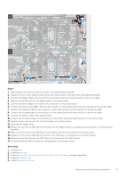
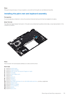
Steps 1. Align and place the system board on the palm-rest and keyboard assembly. 2. Replace the two screws (M2x1.8) that secure the system board to the palm-rest and keyboard assembly. 3. Connect the display cable to the connector on the system board and close the latch to secure the cable. 4. Adhere the tape that secures the display cable to the system board. 5. Connect the power-adapter port cable to the connector on the system board. 6. Connect the keyboard-backlight cable into the connector on the system board and close the latch to secure the cable. 7. Connect the keyboard cable to the connector on the system board and close the latch to secure the cable. 8. Connect the touchpad cable to the connector on the system board and close the latch to secure the cable. 9. Connect the speaker cable to the system board. 10. Connect the I/O-board cable to the connector on the system board and close the latch to secure the cable. 11. Adhere the tape that secures the I/O-board cable to the system board. 12. Close the left display hinge. 13. Replace the two screws (M2.5x3.5) that secure the left display hinge to the system board and palm-rest and keyboard assembly. 14. Align the screw holes on the USB Type-C port bracket with the screw holes on the system board. 15. Replace the two screws (M2.5x3.5) that secure the USB Type-C port bracket to the system board. 16. Adhere the tape that secures the USB Type-C port bracket to the system board. 17. Route the antenna cables through the routing guides on the system board. Next steps 1. Install the fan. 2. Install the heat sink. 3. Install the M.2 2230 solid-state drive or M.2 2280 solid-state drive, whichever applicable. 4. Install the wireless card. 5. Install the memory modules. Removing and installing components 57
-
 1
1 -
2
-
3
-
4
-
5
-
6
-
7
-
8
-
9
-
10
-
11
-
12
-
13
-
14
-
15
-
16
-
17
-
18
-
19
-
20
-
21
-
22
-
23
-
24
-
25
-
26
-
27
-
28
-
29
-
30
-
31
-
32
-
33
-
34
-
35
-
36
-
37
-
38
-
39
-
40
-
41
-
42
-
43
-
44
-
45
-
46
-
47
-
48
-
49
-
50
-
51
-
 52
52 -
 53
53 -
 54
54 -
 55
55 -
 56
56 -
 57
57 -
 58
58 -
 59
59 -
 60
60 -
 61
61 -
 62
62 -
63
-
64
-
65
-
66
-
67
-
68
-
69
-
70
-
71
-
72
-
73
-
74
-
75
-
76
-
77
-
78
-
79
-
80
 |
 |
