Dell Inspiron 14 5410 2-in-1 Service Manual - Page 58
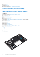
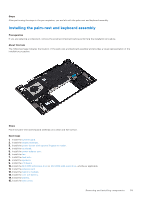
Palm-rest and keyboard assembly
 |
View all Dell Inspiron 14 5410 2-in-1 manuals
Add to My Manuals
Save this manual to your list of manuals |
Page 58 highlights
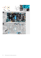
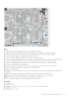
6. Install the battery. 7. Install the base cover. 8. Follow the procedure in After working inside your computer. Palm-rest and keyboard assembly Removing the palm-rest and keyboard assembly Prerequisites 1. Follow the procedure in Before working inside your computer. 2. Remove the base cover. 3. Remove the battery. 4. Remove the coin-cell battery. 5. Remove the memory modules. 6. Remove the wireless card. 7. Remove the M.2 2230 solid-state drive or M.2 2280 solid-state drive, whichever applicable. 8. Remove the I/O board. 9. Remove the speakers. 10. Remove the heat sink. 11. Remove the fan. 12. Remove the touchpad. 13. Remove the power-adapter port. 14. Remove the power button with optional fingerprint reader. 15. Remove the display assembly. 16. Remove the system board. NOTE: The system board can be removed along with the heat sink. About this task The following image indicates the location of the palm-rest and keyboard assembly and provides a visual representation of the removal procedure. 58 Removing and installing components
-
 1
1 -
2
-
3
-
4
-
5
-
6
-
7
-
8
-
9
-
10
-
11
-
12
-
13
-
14
-
15
-
16
-
17
-
18
-
19
-
20
-
21
-
22
-
23
-
24
-
25
-
26
-
27
-
28
-
29
-
30
-
31
-
32
-
33
-
34
-
35
-
36
-
37
-
38
-
39
-
40
-
41
-
42
-
43
-
44
-
45
-
46
-
47
-
48
-
49
-
50
-
51
-
52
-
 53
53 -
 54
54 -
 55
55 -
 56
56 -
 57
57 -
 58
58 -
 59
59 -
 60
60 -
 61
61 -
 62
62 -
 63
63 -
64
-
65
-
66
-
67
-
68
-
69
-
70
-
71
-
72
-
73
-
74
-
75
-
76
-
77
-
78
-
79
-
80
 |
 |
