Dell Latitude C600 Service Manual - Page 19
Removing the Memory Modules, Removing and Replacing Parts - keyboard
 |
View all Dell Latitude C600 manuals
Add to My Manuals
Save this manual to your list of manuals |
Page 19 highlights
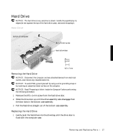
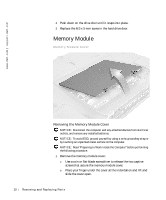
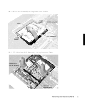
NOTE: The screw labeled with the "circle K" in the middle of the memory module cover secures the keyboard assembly and does not secure the memory module cover. Memory Modules JDIM 1 JDIM 2 inner tabs (2 per socket) memory module sockets (2) Removing the Memory Modules NOTICE: Disconnect the computer and any attached devices from electrical outlets, and remove any installed batteries. NOTICE: To avoid ESD, ground yourself by using a wrist grounding strap or by touching an unpainted metal surface on the computer. Removing and Repl aci ng Part s 19
-
 1
1 -
2
-
3
-
4
-
5
-
6
-
7
-
8
-
9
-
10
-
11
-
12
-
13
-
 14
14 -
 15
15 -
 16
16 -
 17
17 -
 18
18 -
 19
19 -
 20
20 -
 21
21 -
 22
22 -
 23
23 -
 24
24 -
25
-
26
-
27
-
28
-
29
-
30
-
31
-
32
-
33
-
34
-
35
-
36
-
37
-
38
-
39
-
40
-
41
-
42
-
43
-
44
-
45
-
46
-
47
-
48
-
49
-
50
-
51
-
52
-
53
-
54
-
55
-
56
-
57
-
58
-
59
-
60
-
61
-
62
 |
 |
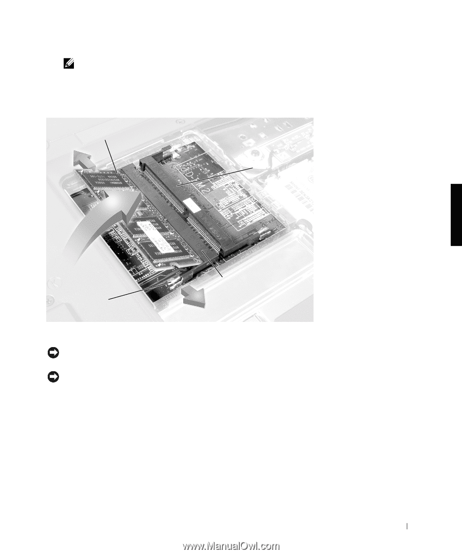
Removing and Replacing Parts
19
NOTE:
The screw labeled with the "circle K" in the middle of the memory
module cover secures the keyboard assembly and does not secure the
memory module cover.
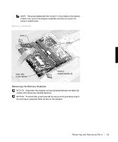
Memory Modules
Removing the Memory Modules
NOTICE:
Disconnect the computer and any attached devices from electrical
outlets, and remove any installed batteries.
NOTICE:
To avoid ESD, ground yourself by using a wrist grounding strap or
by touching an unpainted metal surface on the computer.
memory
module sockets (2)
inner tabs
(2 per socket)
JDIM 1
JDIM 2