Dell Latitude C600 Service Manual - Page 31
Replacing the 14.1-Inch Display Panel - & display inverter
 |
View all Dell Latitude C600 manuals
Add to My Manuals
Save this manual to your list of manuals |
Page 31 highlights
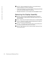
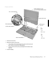
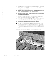
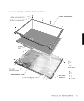
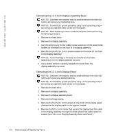
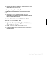
6 Remove the M2 x 4-mm screw that secures the display-feed flex cable to the display assembly through the black plastic flex cable retention bracket (see "14.1-Inch Display Assembly Bezel and Panel"). 7 Disconnect the bottom flex cable connector from the display-assembly top cover and inverter connector by pulling straight up on the attached pull tab. 8 Lift and rotate the top of the display panel out of the display-assembly top cover. Replacing the 14.1-Inch Display Panel 1 Place the bottom edge of the display panel in the bottom of the display-assembly top cover and elevate the top of the panel with your hand. 2 Place the display panel in the display-assembly top cover. 3 Reinstall the five M2 x 4-mm screws that secure the display panel to the display-assembly top cover. Removing and Repl aci ng Part s 31
-
 1
1 -
2
-
3
-
4
-
5
-
6
-
7
-
8
-
9
-
10
-
11
-
12
-
13
-
14
-
15
-
16
-
17
-
18
-
19
-
20
-
21
-
22
-
23
-
24
-
25
-
 26
26 -
 27
27 -
 28
28 -
 29
29 -
 30
30 -
 31
31 -
 32
32 -
 33
33 -
 34
34 -
 35
35 -
 36
36 -
37
-
38
-
39
-
40
-
41
-
42
-
43
-
44
-
45
-
46
-
47
-
48
-
49
-
50
-
51
-
52
-
53
-
54
-
55
-
56
-
57
-
58
-
59
-
60
-
61
-
62
 |
 |
