Dell Latitude C600 Service Manual - Page 45
Hybrid Cooling Fan, the front of the computer, and place it face down on the palmrest.
 |
View all Dell Latitude C600 manuals
Add to My Manuals
Save this manual to your list of manuals |
Page 45 highlights
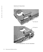
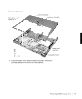
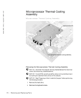
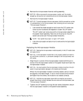
3 Turn the computer over, lift the keyboard up, rotate it forward toward the front of the computer, and place it face down on the palmrest. 4 Loosen the four captive screws securing the microprocessor thermal cooling assembly. 5 Remove the microprocessor thermal cooling assembly from the system board assembly. NOTICE: When reattaching the microprocessor thermal cooling assembly, tighten the captive screws in consecutive order, from 1 to 4. Hybrid Cooling Fan Hybrid Cooling Fan M2.5 x 5-mm screws (2) M2 x 3-mm screw (1) hybrid cooling fan Removing and Repl aci ng Part s 45
-
 1
1 -
2
-
3
-
4
-
5
-
6
-
7
-
8
-
9
-
10
-
11
-
12
-
13
-
14
-
15
-
16
-
17
-
18
-
19
-
20
-
21
-
22
-
23
-
24
-
25
-
26
-
27
-
28
-
29
-
30
-
31
-
32
-
33
-
34
-
35
-
36
-
37
-
38
-
39
-
 40
40 -
 41
41 -
 42
42 -
 43
43 -
 44
44 -
 45
45 -
 46
46 -
 47
47 -
 48
48 -
 49
49 -
 50
50 -
51
-
52
-
53
-
54
-
55
-
56
-
57
-
58
-
59
-
60
-
61
-
62
 |
 |

Removing and Replacing Parts
45
3
Turn the computer over, lift the keyboard up, rotate it forward toward
the front of the computer, and place it face down on the palmrest.
4
Loosen the four captive screws securing the microprocessor thermal
cooling assembly.
5
Remove the microprocessor thermal cooling assembly from the system
board assembly.
NOTICE:
When reattaching the microprocessor thermal cooling assembly,
tighten the captive screws in consecutive order, from 1 to 4.
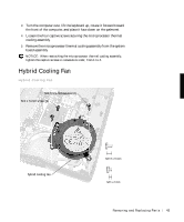
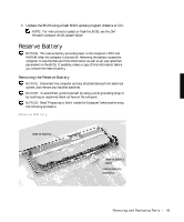
Hybrid Cooling Fan
Hybrid Cooling Fan
M2.5 x 5-mm screws (2)
hybrid cooling fan
M2 x 3-mm screw (1)