Dell Latitude C600 Service Manual - Page 42
edge of the bottom case assembly, underneath the display
 |
View all Dell Latitude C600 manuals
Add to My Manuals
Save this manual to your list of manuals |
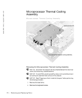
Page 42 highlights
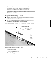
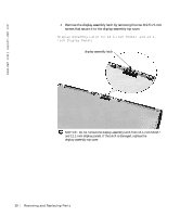
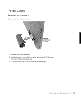
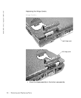
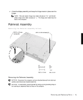
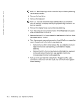
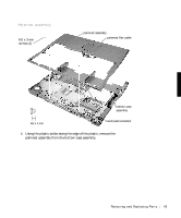
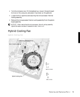
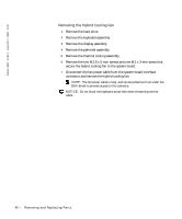
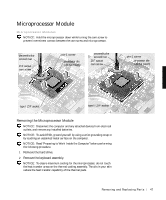
www.dell.com | support.dell.com NOTICE: Read "Preparing to Work Inside the Computer" before performing the following procedure. 1 Remove the hard drive. 2 Remove the keyboard. NOTICE: You must remove the display assembly before you remove the palmrest assembly; the display assembly hinges pass through the back of the palmrest assembly. 3 Remove the display hinge cover and display assembly. 4 Turn the computer over and remove the three M2.5 x 12-mm screws that are labeled with a "circle P." 5 Remove the two M2 x 3-mm screws that are located in the hard drive bay labeled with a "circle P." 6 Turn the computer over, and remove the three M2 x 3-mm screws that secure the palmrest to the bottom case assembly. • Remove the two M2 x 3-mm screws that are located on the back edge of the bottom case assembly, underneath the display assembly. • Remove the M2 x 3-mm screw located underneath the keyboard, on the right side of the bottom case assembly, next to the microprocessor thermal cooling assembly. 7 Pull up on the pull tab that is attached to the palmrest flex cable connector to remove it from the touch pad connector on the system board assembly. 42 Removi ng and Replacing Parts
-
 1
1 -
2
-
3
-
4
-
5
-
6
-
7
-
8
-
9
-
10
-
11
-
12
-
13
-
14
-
15
-
16
-
17
-
18
-
19
-
20
-
21
-
22
-
23
-
24
-
25
-
26
-
27
-
28
-
29
-
30
-
31
-
32
-
33
-
34
-
35
-
36
-
 37
37 -
 38
38 -
 39
39 -
 40
40 -
 41
41 -
 42
42 -
 43
43 -
 44
44 -
 45
45 -
 46
46 -
 47
47 -
48
-
49
-
50
-
51
-
52
-
53
-
54
-
55
-
56
-
57
-
58
-
59
-
60
-
61
-
62
 |
 |
