Dell Latitude C600 Service Manual - Page 41
Palmrest Assembly, Removing the Palmrest Assembly
 |
View all Dell Latitude C600 manuals
Add to My Manuals
Save this manual to your list of manuals |
Page 41 highlights
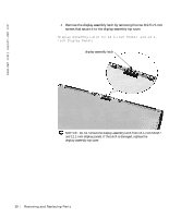
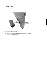
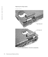
2 Close the display assembly and snap the hinge covers in place over the hinges. NOTE: The right plastic hinge cover label includes an "R," and the left plastic hinge cover label includes an "L." The hinge cover labels face the back of the computer. Palmrest Assembly Removing the Palmrest Assembly Screws M2.5 x 12-mm screws (3) M2 x 3-mm screws (2) Removing the Palmrest Assembly NOTICE: Disconnect the computer and any attached devices from electrical outlets, and remove any installed batteries. NOTICE: To avoid ESD, ground yourself by using a wrist grounding strap or by touching an unpainted metal surface on the computer. Removing and Repl aci ng Part s 41
-
 1
1 -
2
-
3
-
4
-
5
-
6
-
7
-
8
-
9
-
10
-
11
-
12
-
13
-
14
-
15
-
16
-
17
-
18
-
19
-
20
-
21
-
22
-
23
-
24
-
25
-
26
-
27
-
28
-
29
-
30
-
31
-
32
-
33
-
34
-
35
-
 36
36 -
 37
37 -
 38
38 -
 39
39 -
 40
40 -
 41
41 -
 42
42 -
 43
43 -
 44
44 -
 45
45 -
 46
46 -
47
-
48
-
49
-
50
-
51
-
52
-
53
-
54
-
55
-
56
-
57
-
58
-
59
-
60
-
61
-
62
 |
 |
Removing and Replacing Parts
41
2
Close the display assembly and snap the hinge covers in place over the
hinges.
NOTE:
The right plastic hinge cover label includes an “R,” and the left
plastic hinge cover label includes an “L.” The hinge cover labels face the
back of the computer.
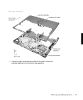
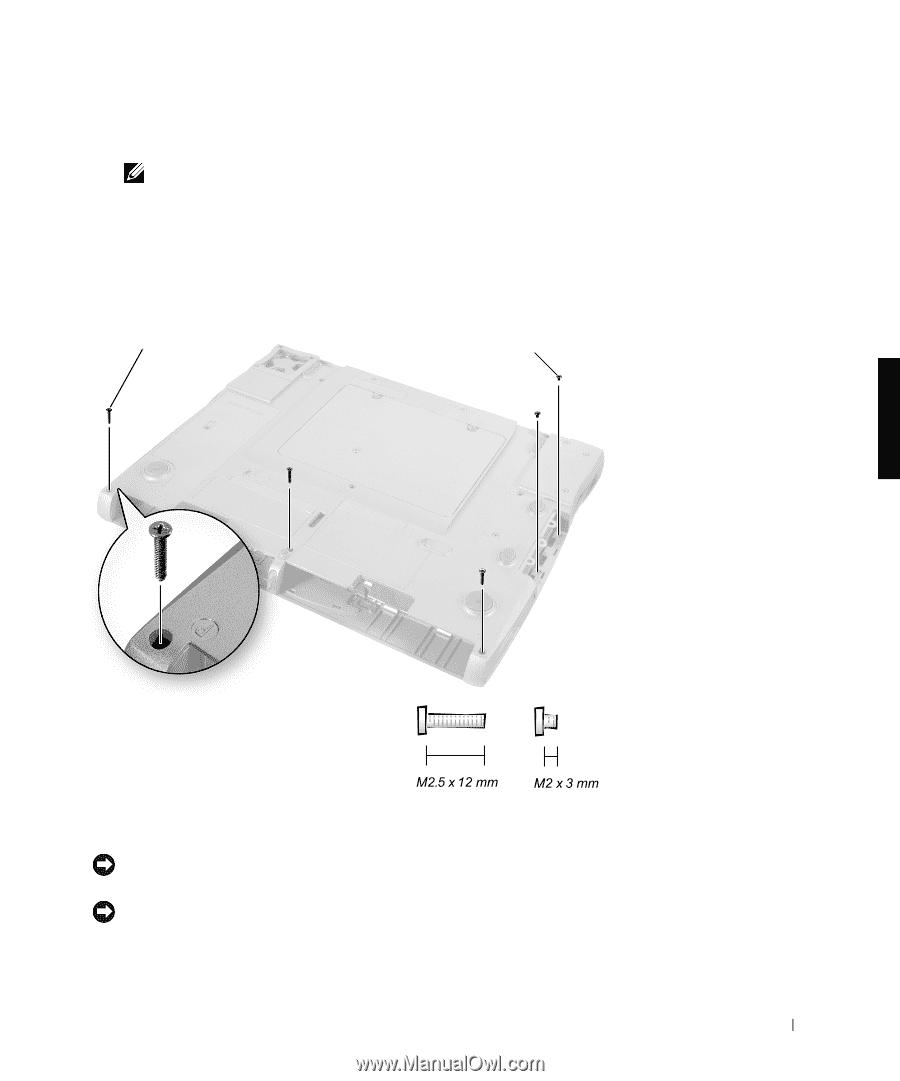
Palmrest Assembly
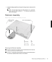
Removing the Palmrest Assembly Screws
Removing the Palmrest Assembly
NOTICE:
Disconnect the computer and any attached devices from electrical
outlets, and remove any installed batteries.
NOTICE:
To avoid ESD, ground yourself by using a wrist grounding strap or
by touching an unpainted metal surface on the computer.
M2.5 x 12-mm
screws (3)
M2 x 3-mm screws (2)