Dell Latitude C600 Service Manual - Page 36
Removing the Display-Feed Flex Cable (12.1-Inch Display Panel)
 |
View all Dell Latitude C600 manuals
Add to My Manuals
Save this manual to your list of manuals |
Page 36 highlights
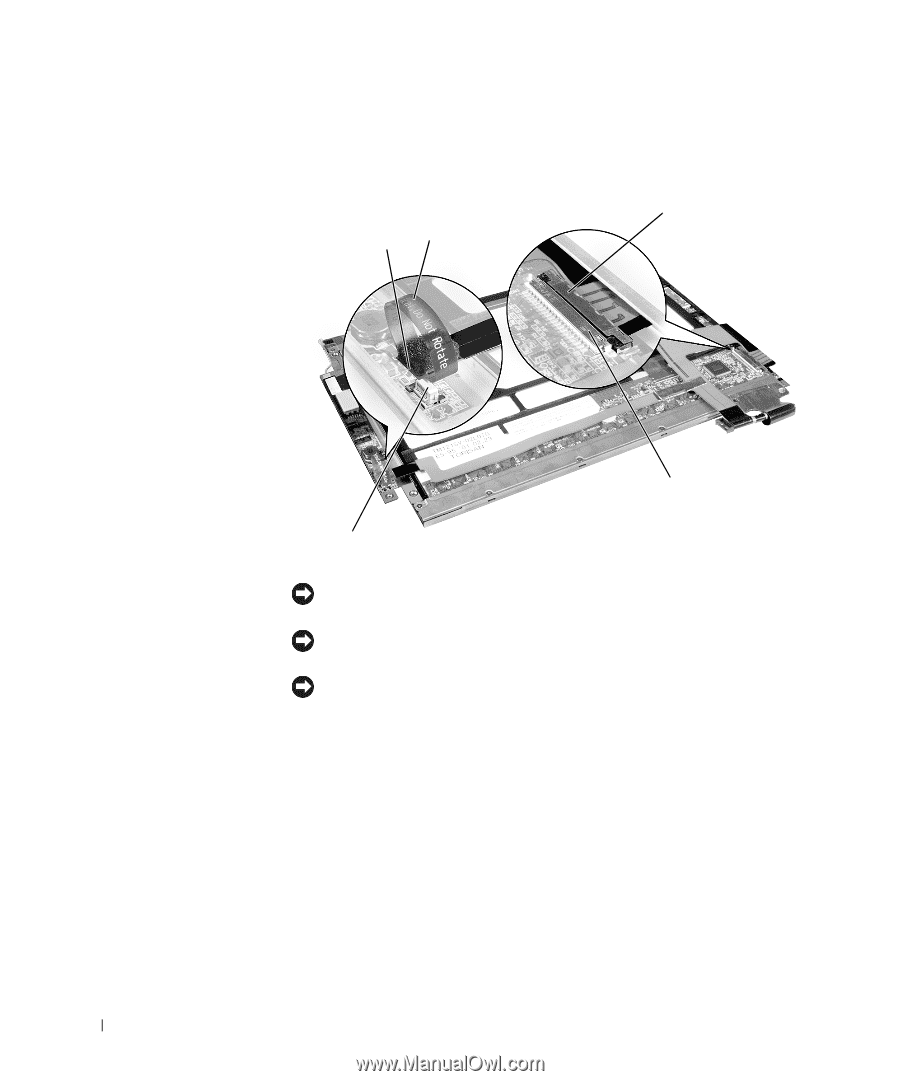
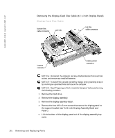
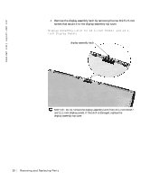
www.dell.com | support.dell.com Removing the Display-Feed Flex Cable (12.1-Inch Display Panel) Display-Feed Flex Cable bottom flex cable connector pull tab top flex cable connector inverter connector display panel connector NOTICE: Disconnect the computer and any attached devices from electrical outlets, and remove any installed batteries. NOTICE: To avoid ESD, ground yourself by using a wrist grounding strap or by touching an unpainted metal surface on the computer. NOTICE: Read "Preparing to Work Inside the Computer" before performing the following procedure. 1 Remove the hard drive. 2 Remove the display assembly. 3 Remove the display assembly bezel. 4 Remove the four M3 x 3-mm screws that secure the display panel to the support bracket (see "12.1-Inch Display Assembly Bezel and Panel"). 5 Lift the bottom of the display panel out of the display-assembly top cover. 36 Removi ng and Replacing Parts
-
 1
1 -
2
-
3
-
4
-
5
-
6
-
7
-
8
-
9
-
10
-
11
-
12
-
13
-
14
-
15
-
16
-
17
-
18
-
19
-
20
-
21
-
22
-
23
-
24
-
25
-
26
-
27
-
28
-
29
-
30
-
 31
31 -
 32
32 -
 33
33 -
 34
34 -
 35
35 -
 36
36 -
 37
37 -
 38
38 -
 39
39 -
 40
40 -
 41
41 -
42
-
43
-
44
-
45
-
46
-
47
-
48
-
49
-
50
-
51
-
52
-
53
-
54
-
55
-
56
-
57
-
58
-
59
-
60
-
61
-
62
 |
 |