Dell Latitude C600 Service Manual - Page 28
to the system board assembly., Remove the two M2 x 3-mm screws that secure the EMI shield bracket
 |
View all Dell Latitude C600 manuals
Add to My Manuals
Save this manual to your list of manuals |
Page 28 highlights
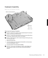
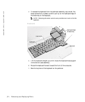
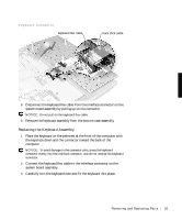
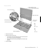
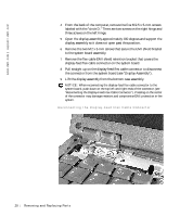
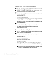
www.dell.com | support.dell.com 4 From the back of the computer, remove the five M2.5 x 5-mm screws labeled with the "circle D." There are two screws on the right hinge and three screws on the left hinge. 5 Open the display assembly approximately 180 degrees and support the display assembly so it does not open past this position. 6 Remove the two M2 x 3-mm screws that secure the EMI shield bracket to the system board assembly. 7 Remove the flex cable EMI shield retention bracket that covers the display-feed flex cable connector on the system board. 8 Pull straight up on the display-feed flex cable connector to disconnect the connector from the system board (see "Display Assembly"). 9 Lift the display assembly from the bottom case assembly. NOTICE: When reconnecting the display-feed flex cable connector to the system board, push down on the top left and right ends of the connector (see "Reconnecting the Display-Feed Flex Cable Connector"). Pressing on the center of the connector may damage resistors and compromise EMI protection in the system. Reconnecting the Display-Feed Flex Cable Connector 28 Removi ng and Replacing Parts
-
 1
1 -
2
-
3
-
4
-
5
-
6
-
7
-
8
-
9
-
10
-
11
-
12
-
13
-
14
-
15
-
16
-
17
-
18
-
19
-
20
-
21
-
22
-
 23
23 -
 24
24 -
 25
25 -
 26
26 -
 27
27 -
 28
28 -
 29
29 -
 30
30 -
 31
31 -
 32
32 -
 33
33 -
34
-
35
-
36
-
37
-
38
-
39
-
40
-
41
-
42
-
43
-
44
-
45
-
46
-
47
-
48
-
49
-
50
-
51
-
52
-
53
-
54
-
55
-
56
-
57
-
58
-
59
-
60
-
61
-
62
 |
 |
