Dell Latitude C600 Service Manual - Page 27
Remove the center control cover., Remove the hard drive.
 |
View all Dell Latitude C600 manuals
Add to My Manuals
Save this manual to your list of manuals |
Page 27 highlights
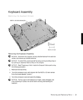
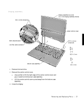
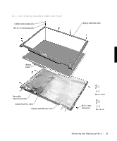
Display Assembly M2 x 3-mm screws (2) EMI shield bracket LCD flex cable connector display-assembly top cover (14.1-inch display assembly shown) center control cover M2.5 x 5-mm screws (5) bottom case assembly 1 Remove the hard drive. 2 Remove the center control cover. a Use a scribe to lift the right edge of the center control cover and pry it loose from the bottom case assembly. b Lift the center control cover up and away from the bottom case assembly. 3 Close the display. Removing and Repl aci ng Part s 27
-
 1
1 -
2
-
3
-
4
-
5
-
6
-
7
-
8
-
9
-
10
-
11
-
12
-
13
-
14
-
15
-
16
-
17
-
18
-
19
-
20
-
21
-
 22
22 -
 23
23 -
 24
24 -
 25
25 -
 26
26 -
 27
27 -
 28
28 -
 29
29 -
 30
30 -
 31
31 -
 32
32 -
33
-
34
-
35
-
36
-
37
-
38
-
39
-
40
-
41
-
42
-
43
-
44
-
45
-
46
-
47
-
48
-
49
-
50
-
51
-
52
-
53
-
54
-
55
-
56
-
57
-
58
-
59
-
60
-
61
-
62
 |
 |

Removing and Replacing Parts
27
Display Assembly
1
Remove the hard drive.
2
Remove the center control cover.
a
Use a scribe to lift the right edge of the center control cover and
pry it loose from the bottom case assembly.
b
Lift the center control cover up and away from the bottom case
assembly.
3
Close the display.
M2.5 x 5-mm
screws (5)
LCD flex cable connector
bottom case assembly
center control cover
EMI shield bracket
display-assembly top cover
(14.1-inch display assembly shown)
M2 x 3-mm screws (2)