Dell Latitude C600 Service Manual - Page 22
Removing the Mini-PCI Card Assembly, Depending on the type of mini-PCI card you are installing, either - wireless cards
 |
View all Dell Latitude C600 manuals
Add to My Manuals
Save this manual to your list of manuals |
Page 22 highlights
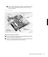
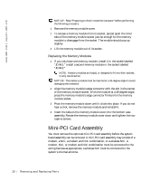
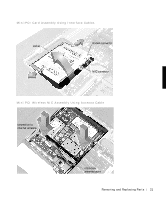
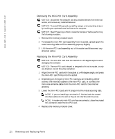
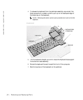
www.dell.com | support.dell.com Removing the Mini-PCI Card Assembly NOTICE: Disconnect the computer and any attached devices from electrical outlets, and remove any installed batteries. NOTICE: To avoid ESD, ground yourself by using a wrist grounding strap or by touching an unpainted metal surface on the computer. NOTICE: Read "Preparing to Work Inside the Computer" before performing the following procedure. 1 Remove the memory module cover. 2 To release the mini-PCI card assembly from its socket, spread apart the metal securing tabs until the assembly pops up slightly. 3 Lift the mini-PCI card assembly out of its socket and disconnect any attached cables. Replacing the Mini-PCI Card Assembly NOTICE: The mini-PCI card must be inserted at a 45-degree angle to avoid damaging the connector. NOTICE: The mini-PCI card is keyed, or designed to fit into its socket, in only one direction. Do not force the connection. 1 Align the mini-PCI card with the socket at a 45-degree angle, and press the mini-PCI card firmly into the socket. 2 Depending on the type of mini-PCI card you are installing, either connect the interface cables to the mini-PCI card, or connect the mini-coax antenna cable from the mini-PCI card to the internal antenna. 3 Lower the mini-PCI card until it snaps into the metal securing tabs. NOTE: If you are installing a wireless NIC, fold and tuck the unused interface cables into the slot so they do not interfere with the cover. NOTE: A modem-only mini-PCI card has one connector; place the unused NIC connector under the mini-PCI card. 4 Replace the memory module cover. 22 Removi ng and Replacing Parts
-
 1
1 -
2
-
3
-
4
-
5
-
6
-
7
-
8
-
9
-
10
-
11
-
12
-
13
-
14
-
15
-
16
-
 17
17 -
 18
18 -
 19
19 -
 20
20 -
 21
21 -
 22
22 -
 23
23 -
 24
24 -
 25
25 -
 26
26 -
 27
27 -
28
-
29
-
30
-
31
-
32
-
33
-
34
-
35
-
36
-
37
-
38
-
39
-
40
-
41
-
42
-
43
-
44
-
45
-
46
-
47
-
48
-
49
-
50
-
51
-
52
-
53
-
54
-
55
-
56
-
57
-
58
-
59
-
60
-
61
-
62
 |
 |