Dell PowerEdge R340 EMC PowerEdge R340 Installation and Service Manual - Page 10
Rear view of the system, Inside the system
 |
View all Dell PowerEdge R340 manuals
Add to My Manuals
Save this manual to your list of manuals |
Page 10 highlights
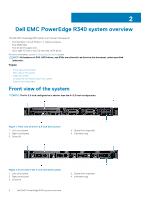
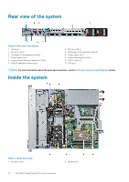
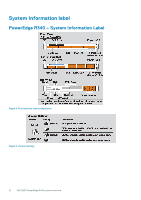
Rear view of the system Figure 5. Rear view of the system 1. Serial port 3. NIC port (GB 2) 5. Full-height PCIe expansion card slot 7. Power supply unit 2 9. System status indicator cable port (CMA) 11. iDRAC9 dedicated network port 2. NIC port (GB 1) 4. Half-height PCIe expansion card slot 6. Power supply unit 1 8. System identification button 10. USB 3.0 port (2) 12. VGA port NOTE: For more information about the ports and connectors, see the Ports and connectors specifications section. Inside the system Figure 6. Inside the system 1. Intrusion switch 2. Optical drive 10 Dell EMC PowerEdge R340 system overview
-
 1
1 -
2
-
3
-
4
-
 5
5 -
 6
6 -
 7
7 -
 8
8 -
 9
9 -
 10
10 -
 11
11 -
 12
12 -
 13
13 -
 14
14 -
 15
15 -
16
-
17
-
18
-
19
-
20
-
21
-
22
-
23
-
24
-
25
-
26
-
27
-
28
-
29
-
30
-
31
-
32
-
33
-
34
-
35
-
36
-
37
-
38
-
39
-
40
-
41
-
42
-
43
-
44
-
45
-
46
-
47
-
48
-
49
-
50
-
51
-
52
-
53
-
54
-
55
-
56
-
57
-
58
-
59
-
60
-
61
-
62
-
63
-
64
-
65
-
66
-
67
-
68
-
69
-
70
-
71
-
72
-
73
-
74
-
75
-
76
-
77
-
78
-
79
-
80
-
81
-
82
-
83
-
84
-
85
-
86
-
87
-
88
-
89
-
90
-
91
-
92
-
93
-
94
-
95
-
96
-
97
-
98
-
99
-
100
-
101
-
102
-
103
-
104
-
105
-
106
-
107
-
108
-
109
-
110
-
111
-
112
-
113
-
114
-
115
-
116
-
117
-
118
 |
 |

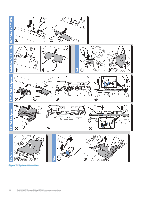
Rear view of the system
Figure 5. Rear view of the system
1.
Serial port
2.
NIC port (GB 1)
3.
NIC port (GB 2)
4.
Half-height PCIe expansion card slot
5.
Full-height PCIe expansion card slot
6.
Power supply unit 1
7.
Power supply unit 2
8.
System identification button
9.
System status indicator cable port (CMA)
10.
USB 3.0 port (2)
11.
iDRAC9 dedicated network port
12.
VGA port
NOTE:
For more information about the ports and connectors, see the
Ports and connectors specifications
section.
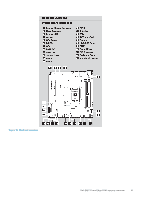
Inside the system
Figure 6. Inside the system
1.
Intrusion switch
2.
Optical drive
10
Dell EMC PowerEdge R340 system overview