Dell PowerEdge T340 EMC Installation and Service Manual - Page 12
Inside the system
 |
View all Dell PowerEdge T340 manuals
Add to My Manuals
Save this manual to your list of manuals |
Page 12 highlights
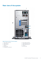
Figure 4. Rear view of 4 x 3.5-inch drive system 1. Cabled power supply unit (PSU) 3. System identification button 5. iDRAC dedicated NIC port 7. Serial port 9. NIC port (Gb2) 2. USB 2.0 port (4) 4. USB 3.0 port (2) 6. VGA port 8. NIC port (Gb1) 10. PCIe expansion card slots (4) NOTE: For more information about the ports and connectors, see the Ports and connectors specifications section. Inside the system NOTE: Components that are hot swappable are marked orange and touch points on the components are marked blue. 12 Dell EMC PowerEdge T340 system overview
-
 1
1 -
2
-
3
-
4
-
5
-
6
-
 7
7 -
 8
8 -
 9
9 -
 10
10 -
 11
11 -
 12
12 -
 13
13 -
 14
14 -
 15
15 -
 16
16 -
 17
17 -
18
-
19
-
20
-
21
-
22
-
23
-
24
-
25
-
26
-
27
-
28
-
29
-
30
-
31
-
32
-
33
-
34
-
35
-
36
-
37
-
38
-
39
-
40
-
41
-
42
-
43
-
44
-
45
-
46
-
47
-
48
-
49
-
50
-
51
-
52
-
53
-
54
-
55
-
56
-
57
-
58
-
59
-
60
-
61
-
62
-
63
-
64
-
65
-
66
-
67
-
68
-
69
-
70
-
71
-
72
-
73
-
74
-
75
-
76
-
77
-
78
-
79
-
80
-
81
-
82
-
83
-
84
-
85
-
86
-
87
-
88
-
89
-
90
-
91
-
92
-
93
-
94
-
95
-
96
-
97
-
98
-
99
-
100
-
101
-
102
-
103
-
104
-
105
-
106
-
107
-
108
-
109
-
110
-
111
-
112
-
113
-
114
-
115
-
116
-
117
-
118
-
119
-
120
-
121
-
122
-
123
-
124
-
125
-
126
 |
 |
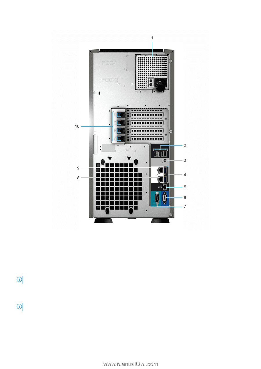
Figure 4. Rear view of 4 x 3.5-inch drive system
1.
Cabled power supply unit (PSU)
2.
USB 2.0 port (4)
3.
System identification button
4.
USB 3.0 port (2)
5.
iDRAC dedicated NIC port
6.
VGA port
7.
Serial port
8.
NIC port (Gb1)
9.
NIC port (Gb2)
10.
PCIe expansion card slots (4)
NOTE:
For more information about the ports and connectors, see the
Ports and connectors specifications
section.
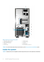
Inside the system
NOTE:
Components that are hot swappable are marked orange and touch points on the components are marked blue.
12
Dell EMC PowerEdge T340 system overview