Dell PowerEdge T340 EMC Installation and Service Manual - Page 13
Inside the system with cabled power supply unit PSU, Inside the system
 |
View all Dell PowerEdge T340 manuals
Add to My Manuals
Save this manual to your list of manuals |
Page 13 highlights
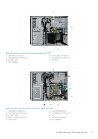
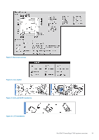
Figure 5. Inside the system with cabled power supply unit (PSU) 1. Optical drive or tape drive 3. PCIe Expansion card latch (4) 5. Intrusion switch 7. Drive backplane 2. Power supply unit (cabled) 4. PCIe Expansion card slots (4) 6. Air shroud Figure 6. Inside the system with redundant power supply unit (PSU) 1. Optical drive or tape drive 3. PCIe Expansion card latch (4) 5. Intrusion switch 7. Memory module socket (4) 9. System board 2. Power interposer board 4. PCIe Expansion card slots (4) 6. Fan 8. Processor and heat sink 10. Drive backplane Dell EMC PowerEdge T340 system overview 13
-
 1
1 -
2
-
3
-
4
-
5
-
6
-
7
-
 8
8 -
 9
9 -
 10
10 -
 11
11 -
 12
12 -
 13
13 -
 14
14 -
 15
15 -
 16
16 -
 17
17 -
 18
18 -
19
-
20
-
21
-
22
-
23
-
24
-
25
-
26
-
27
-
28
-
29
-
30
-
31
-
32
-
33
-
34
-
35
-
36
-
37
-
38
-
39
-
40
-
41
-
42
-
43
-
44
-
45
-
46
-
47
-
48
-
49
-
50
-
51
-
52
-
53
-
54
-
55
-
56
-
57
-
58
-
59
-
60
-
61
-
62
-
63
-
64
-
65
-
66
-
67
-
68
-
69
-
70
-
71
-
72
-
73
-
74
-
75
-
76
-
77
-
78
-
79
-
80
-
81
-
82
-
83
-
84
-
85
-
86
-
87
-
88
-
89
-
90
-
91
-
92
-
93
-
94
-
95
-
96
-
97
-
98
-
99
-
100
-
101
-
102
-
103
-
104
-
105
-
106
-
107
-
108
-
109
-
110
-
111
-
112
-
113
-
114
-
115
-
116
-
117
-
118
-
119
-
120
-
121
-
122
-
123
-
124
-
125
-
126
 |
 |
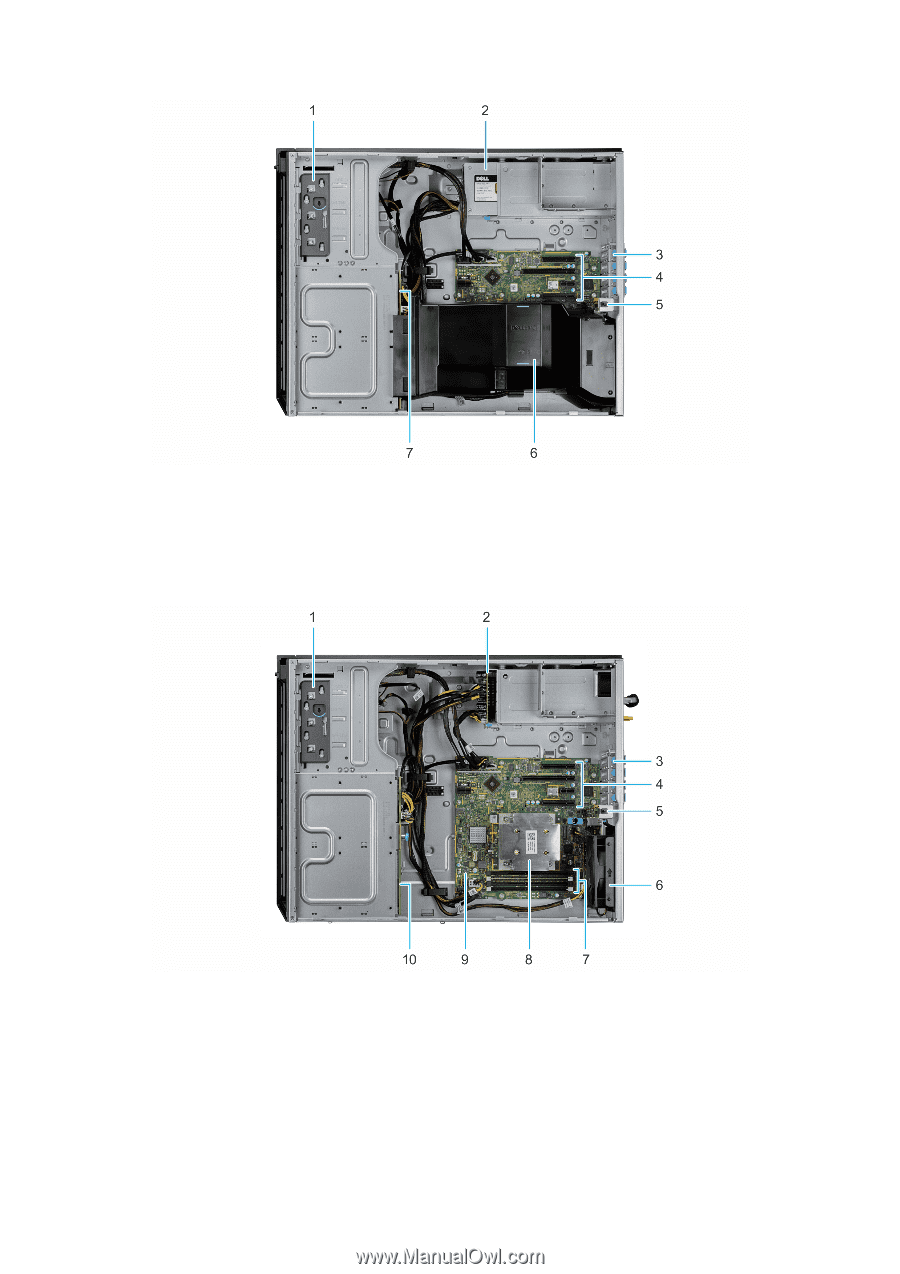
Figure 5. Inside the system with cabled power supply unit (PSU)
1.
Optical drive or tape drive
2.
Power supply unit (cabled)
3.
PCIe Expansion card latch (4)
4.
PCIe Expansion card slots (4)
5.
Intrusion switch
6.
Air shroud
7.
Drive backplane
Figure 6. Inside the system with redundant power supply unit (PSU)
1.
Optical drive or tape drive
2.
Power interposer board
3.
PCIe Expansion card latch (4)
4.
PCIe Expansion card slots (4)
5.
Intrusion switch
6.
Fan
7.
Memory module socket (4)
8.
Processor and heat sink
9.
System board
10.
Drive backplane
Dell EMC PowerEdge T340 system overview
13