Dell PowerEdge T440 EMC Installation and Service Manual - Page 16
Status LED indicators - memory slots
 |
View all Dell PowerEdge T440 manuals
Add to My Manuals
Save this manual to your list of manuals |
Page 16 highlights
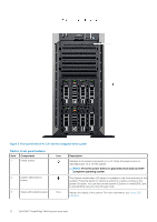
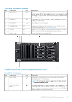
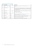
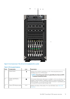
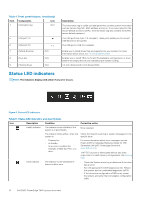
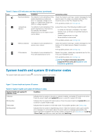
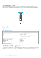
Table 4. Front panel features (continued) Item Components Icon 4 Information tag N/A 5 USB port 2.0 6 USB port 3.0 7 Optical drive bay N/A 8 Drive slot N/A 9 Physical drives N/A Description The Information tag is a slide-out label panel that contains system information such as Service Tag, NIC, MAC address, and so on. If you have opted for the secure default access to iDRAC, the Information tag also contains the iDRAC secure default password. The USB ports are 4-pin, 2.0-compliant. These ports enable you to connect USB devices to the system. The USB port is USB 3.0 compliant. Enable you to install drives that are supported on your system. For more information about drives, see Technical specifications. Enables you to install TBUs for 8x and 16x backplane configurations, or drive blank in the empty drive slot to maintain proper system cooling. 3.5-inch drives and 2.5-inch drives/SSDs. Status LED indicators NOTE: The indicators display solid amber if any error occurs. Figure 6. Status LED indicators Table 5. Status LED indicators and descriptions Icon Description Condition Corrective action Health indicator The indicator turns solid blue if the system is in good health. None required. The indicator blinks amber, when the Check the System event log or system messages for the system is: specific issue. • Powered on • In standby • In any error condition For example, a failed fan, PSU, or a drive For more information about error messages, see the Event and Error Message Reference Guide for 14th Generation Dell EMC PowerEdge Servers at www.dell.com/qrl. The POST process is interrupted without any video output due to invalid memory configurations. See Getting help. Drive indicator The indicator turns solid amber if there is a drive error. • Check the System event log to determine if the drive has an error. • Run the appropriate Online Diagnostics test. Restart the system, and run embedded diagnostics (ePSA. • If the drives are configured in a RAID array, restart the system, and enter the host adapter configuration utility. 16 Dell EMC PowerEdge T440 system overview
-
 1
1 -
2
-
3
-
4
-
5
-
6
-
7
-
8
-
9
-
10
-
 11
11 -
 12
12 -
 13
13 -
 14
14 -
 15
15 -
 16
16 -
 17
17 -
 18
18 -
 19
19 -
 20
20 -
 21
21 -
22
-
23
-
24
-
25
-
26
-
27
-
28
-
29
-
30
-
31
-
32
-
33
-
34
-
35
-
36
-
37
-
38
-
39
-
40
-
41
-
42
-
43
-
44
-
45
-
46
-
47
-
48
-
49
-
50
-
51
-
52
-
53
-
54
-
55
-
56
-
57
-
58
-
59
-
60
-
61
-
62
-
63
-
64
-
65
-
66
-
67
-
68
-
69
-
70
-
71
-
72
-
73
-
74
-
75
-
76
-
77
-
78
-
79
-
80
-
81
-
82
-
83
-
84
-
85
-
86
-
87
-
88
-
89
-
90
-
91
-
92
-
93
-
94
-
95
-
96
-
97
-
98
-
99
-
100
-
101
-
102
-
103
-
104
-
105
-
106
-
107
-
108
-
109
-
110
-
111
-
112
-
113
-
114
-
115
-
116
-
117
-
118
-
119
-
120
-
121
-
122
-
123
-
124
-
125
-
126
-
127
-
128
-
129
-
130
-
131
-
132
-
133
-
134
-
135
-
136
-
137
-
138
-
139
-
140
-
141
-
142
-
143
-
144
-
145
-
146
-
147
 |
 |