Dell PowerEdge T440 EMC Installation and Service Manual - Page 67
Caster wheels – optional, Removing caster wheels
 |
View all Dell PowerEdge T440 manuals
Add to My Manuals
Save this manual to your list of manuals |
Page 67 highlights
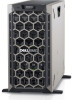
3. cable retention lock 5. power supply unit cage 7. processor 2 socket 9. cabled drive cage 4. cabled power supply unit 6. fan 8. processor 1 Figure 21. Inside the system - hot swappable drive system 1. release latch 2. drive cage 3. cable retention lock 4. power interposer board 5. power supply unit cage 6. fan 7. processor 2 socket 8. processor 1 9. backplane Caster wheels - optional Removing caster wheels Prerequisites 1. Follow the safety guidelines listed in Safety instructions. 2. Place the system on a flat, stable surface. 3. Extend the wheels beyond the edge of the surface. Steps 1. Using the Phillips #2 screwdriver, loosen the captive screw that secures the front wheel unit to the base of the system. 2. Push the front wheel unit toward the rear of the system to release the retention hooks, and pull out the front wheel unit. 3. Loosen the screw that secures the back wheel unit to the base of the chassis. 4. Push the rear wheel unit toward the front of the system to release the retention hooks, and pull out the rear wheel unit. Installing and removing system components 67
-
 1
1 -
2
-
3
-
4
-
5
-
6
-
7
-
8
-
9
-
10
-
11
-
12
-
13
-
14
-
15
-
16
-
17
-
18
-
19
-
20
-
21
-
22
-
23
-
24
-
25
-
26
-
27
-
28
-
29
-
30
-
31
-
32
-
33
-
34
-
35
-
36
-
37
-
38
-
39
-
40
-
41
-
42
-
43
-
44
-
45
-
46
-
47
-
48
-
49
-
50
-
51
-
52
-
53
-
54
-
55
-
56
-
57
-
58
-
59
-
60
-
61
-
 62
62 -
 63
63 -
 64
64 -
 65
65 -
 66
66 -
 67
67 -
 68
68 -
 69
69 -
 70
70 -
 71
71 -
 72
72 -
73
-
74
-
75
-
76
-
77
-
78
-
79
-
80
-
81
-
82
-
83
-
84
-
85
-
86
-
87
-
88
-
89
-
90
-
91
-
92
-
93
-
94
-
95
-
96
-
97
-
98
-
99
-
100
-
101
-
102
-
103
-
104
-
105
-
106
-
107
-
108
-
109
-
110
-
111
-
112
-
113
-
114
-
115
-
116
-
117
-
118
-
119
-
120
-
121
-
122
-
123
-
124
-
125
-
126
-
127
-
128
-
129
-
130
-
131
-
132
-
133
-
134
-
135
-
136
-
137
-
138
-
139
-
140
-
141
-
142
-
143
-
144
-
145
-
146
-
147
 |
 |
