Epson 585Wi Installation Guide - Ultra-Short Throw Wall Mount (ELPMB43)
Epson 585Wi Manual
 |
View all Epson 585Wi manuals
Add to My Manuals
Save this manual to your list of manuals |
Epson 585Wi manual content summary:
- Epson 585Wi | Installation Guide - Ultra-Short Throw Wall Mount (ELPMB43) - Page 1
Installation Guide Guide d'installation - Epson 585Wi | Installation Guide - Ultra-Short Throw Wall Mount (ELPMB43) - Page 2
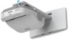
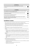
Unit after wall mount installation. The following projectors are covered by this guide: • BrightLink® 475Wi/480i/485Wi/575Wi/585Wi/595Wi and 575Wi+/585Wi+/595Wi+ • BrightLink Pro 1410Wi/1420Wi/1430Wi • PowerLite® 470/475W/480/485W/570/575W/580/585W Safety Instructions For your safety, read all the - Epson 585Wi | Installation Guide - Ultra-Short Throw Wall Mount (ELPMB43) - Page 3
at least two qualified service personnel. If you need to loosen any screws during installation, be careful not to drop the wall mount. If the wall mount or projector falls, it could cause personal injury or property damage. Install the wall mount so that it can sufficiently support the weight of the - Epson 585Wi | Installation Guide - Ultra-Short Throw Wall Mount (ELPMB43) - Page 4
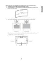
(20 cm) from the edge of the screen. • Make sure there are no obstacles between the Control Pad and the projector (not including the Touch Unit). • Use the optional Remote Control Cable Set (model ELPKC28, part number V12H005C28) to supply power to the Control Pad in the following situations: • The - Epson 585Wi | Installation Guide - Ultra-Short Throw Wall Mount (ELPMB43) - Page 5
of the whiteboard. Correct position Incorrect position Make sure there are no obstacles, such as cables, or protruding objects such as whiteboard trays, pen holders, or thick frames in the shaded areas in the following figure. The Touch Unit will not operate correctly if anything is obstructing - Epson 585Wi | Installation Guide - Ultra-Short Throw Wall Mount (ELPMB43) - Page 6
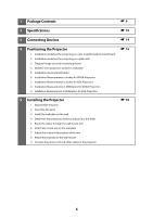
Measurements in Inches for WXGA Projectors 7. Installation Measurements in Inches for XGA Projectors 8. Installation Measurements in Millimeters for WXGA Projectors 9. nstallation Measurements in Millimeters for XGA Projectors 5 Installing the Projector 1. Disassemble the parts 2. Assemble the - Epson 585Wi | Installation Guide - Ultra-Short Throw Wall Mount (ELPMB43) - Page 7
Image 1. Turn on the projector 2. Display the test pattern 3. Change the aspect ratio if necessary 4. Adjust the focus 5. Use the adjustment cover 2. Attach the Control Pad 3. Install the batteries 4. Connect the projector cables to the Control Pad 5. Attach the port protection stickers 6. Attach - Epson 585Wi | Installation Guide - Ultra-Short Throw Wall Mount (ELPMB43) - Page 8
sheet (for installing the wall plate) VGA computer cable (may be included with projector or wall mount) Open-ended wrench 13 mm (for M8 and M6) × bolts or screws supplied with the wall mount to install it as directed in this guide. Do not substitute these bolts with any other types. • You need to - Epson 585Wi | Installation Guide - Ultra-Short Throw Wall Mount (ELPMB43) - Page 9
2.4 inches [6 cm]) for securing the markers (×12) Infrared deflector (approx. 11.2 inches [28.5 cm]) (×8) Control Pad The following parts are packaged with your projector and are necessary when attaching the Control Pad. When installing the Control Pad on a wall, you will also need four M4 × 20 mm - Epson 585Wi | Installation Guide - Ultra-Short Throw Wall Mount (ELPMB43) - Page 10
is in three pieces when shipped. Use the included M4 × 12 mm bolts (×6) to attach the separate pieces together before mounting the projector. See page 31 for instructions. 3.1 in. (79 mm) 6.3 in. (160 mm) 8.4 in. (213 mm) 8.7 in. (222 mm) 9.7 in. (246 mm) 5.1 in. (130 mm) 1.0 in. (25 mm) 1.2 in - Epson 585Wi | Installation Guide - Ultra-Short Throw Wall Mount (ELPMB43) - Page 11
installation position By changing the installation position of the 3-axis adjustment unit to the front or back, you can adjust the installation position of the projector. When the screen size is less than 75 inches, install it at the position marked with a stamp on the mount arm. When the screen - Epson 585Wi | Installation Guide - Ultra-Short Throw Wall Mount (ELPMB43) - Page 12
Touch Unit External dimensions and weight The Touch Unit weighs approximately 16 ounces (450 g). 3.7 in. (95 mm) 8.3 in. (210 mm) 2.0 in. (51 mm) Attached labels The Touch Unit is a Class 1 laser product that conforms to the JIS C 6802:2011 standard. There are warning labels affixed to the Touch - Epson 585Wi | Installation Guide - Ultra-Short Throw Wall Mount (ELPMB43) - Page 13
English Control Pad External dimensions and weight The Control Pad weighs approximately 8.5 ounces (240 g). 5.4 in (135.9 mm) 0.4 in (11.5 mm) 4.4 in (111 mm) 4.3 in (109 mm) 0.1 in (3.5 mm) 4.2 in (107 mm) 4.0 in (104 mm) 5.9 in (149 mm) 6.0 in (153.5 mm) 0,6 in (15.47 mm) 1.1 in (29 mm) - Epson 585Wi | Installation Guide - Ultra-Short Throw Wall Mount (ELPMB43) - Page 14
may differ slightly from the displayed model. For details, refer to the online User's Guide for your projector. Connection Example External speakers Audio cable (not included) Microphone Document camera (Epson DC-06) Touch Unit LAN cable (not included) Touch Unit connection cable LAN device - Epson 585Wi | Installation Guide - Ultra-Short Throw Wall Mount (ELPMB43) - Page 15
. You must install the control pad on the same surface as the projector, within the range specified in the installation instructions. You can use the included batteries to power the control pad, or the optional remote control cable set (model ELPKC28, part number V12H005C28). See "Installing the - Epson 585Wi | Installation Guide - Ultra-Short Throw Wall Mount (ELPMB43) - Page 16
4 Positioning the Projector BrightLink Pro 1410Wi/1420Wi/1430Wi, BrightLink 475W/485W, BrightLink 575Wi/585Wi/595Wi, BrightLink 575Wi+/585Wi+/595Wi+ and PowerLite 475W such as cables, whiteboard trays, pen holders, or frames within the areas listed above, the Touch Unit will not operate properly. 16 - Epson 585Wi | Installation Guide - Ultra-Short Throw Wall Mount (ELPMB43) - Page 17
area and the bottom holes of _____ (c) the wall plate (c). 9. Determine the position for your projector installation by adding the values for (f), (h), _____ (f ) and (c), plus an additional 10 with the center of the image area. Follow the instructions on page 30 to install the projector. 17 - Epson 585Wi | Installation Guide - Ultra-Short Throw Wall Mount (ELPMB43) - Page 18
Installation worksheet for projecting on a plain wall 1. Measure the ceiling height (distance from the floor to the ceiling). _____ 2. Determine the desired aspect ratio of the image. For new computers or laptops, this will most likely be WXGA (16:10). For older equipment, this will most likely - Epson 585Wi | Installation Guide - Ultra-Short Throw Wall Mount (ELPMB43) - Page 19
the center line on the template sheet with the center of the image area. Follow the instructions on page 30 to install the projector. The tables on the following pages provide installation information for all supported image sizes. The minimum ceiling height is based on an image 30 inches from the - Epson 585Wi | Installation Guide - Ultra-Short Throw Wall Mount (ELPMB43) - Page 20
1410Wi/1420Wi/1430Wi BrightLink 475W/485W/575Wi/585Wi/595Wi 100 BrightLink 575Wi+/585Wi+/595Wi+ WXGA PowerLite 475W/485W/575W/585W BrightLink 480i PowerLite 470/480/570/580 93 XGA The measurements may differ depending on the location where you place the projector. When projecting in Tele, the - Epson 585Wi | Installation Guide - Ultra-Short Throw Wall Mount (ELPMB43) - Page 21
21 Installation Measurements in Inches for WXGA Projectors Diagonal image size (S) Min. ceiling height* Image width (w) 16:10 WXGA Image Min. Slider height projection scale (h) distance mark (a) (b) Distance Min. from top of ceiling - Epson 585Wi | Installation Guide - Ultra-Short Throw Wall Mount (ELPMB43) - Page 22
Diagonal image size (S) Min. ceiling height* Image width (w) 16:10 WXGA Image Min. Slider Distance Min. height projection scale from top of ceiling (h) distance mark image to height* (a) (b) wall plate holes (c) Image width (w) 4:3 XGA Image height (h) Min. projection distance (a) - Epson 585Wi | Installation Guide - Ultra-Short Throw Wall Mount (ELPMB43) - Page 23
23 Installation Measurements in Inches for XGA Projectors Diagonal image size (S) Min. ceiling height* Image width (w) 4:3 XGA Image Min. Slider Distance height projection scale from top of (h) distance (a) mark image to (b) wall plate - Epson 585Wi | Installation Guide - Ultra-Short Throw Wall Mount (ELPMB43) - Page 24
Diagonal image size (S) Min. ceiling height* Image width (w) 4:3 XGA Image Min. Slider Distance height projection scale from top of (h) distance (a) mark image to (b) wall plate holes (c) 16:10 WXGA Min. Image Image Min. ceiling width height projectio height* (w) (h) n distance (a) Slider - Epson 585Wi | Installation Guide - Ultra-Short Throw Wall Mount (ELPMB43) - Page 25
25 Installation Measurements in Millimeters for WXGA Projectors Diagonal image size (S) Min. ceiling height* 16:10 WXGA Image Image Min. width height projection (w) (h) distance (a) Slider scale mark (b) Distance from top of image to - Epson 585Wi | Installation Guide - Ultra-Short Throw Wall Mount (ELPMB43) - Page 26
Diagonal image size (S) Min. ceiling height* 16:10 WXGA Image Image Min. width height projection (w) (h) distance (a) Slider scale mark (b) Distance from top of image to wall plate holes (c) Min. ceiling height* Image width (w) 4:3 XGA Image Min. Slider Distance height projection scale from - Epson 585Wi | Installation Guide - Ultra-Short Throw Wall Mount (ELPMB43) - Page 27
27 nstallation Measurements in Millimeters for XGA Projectors Diagonal image size (S) 4:3 XGA Min. Image Image Min. ceiling width height projection height* (w) (h) distance (a) Slider Distance scale from top of mark image to (b) wall plate - Epson 585Wi | Installation Guide - Ultra-Short Throw Wall Mount (ELPMB43) - Page 28
Diagonal image size (S) 4:3 XGA Min. Image Image Min. Slider Distance ceiling width height projection scale from top of height* (w) (h) distance mark image to (a) (b) wall plate holes (c) Min. ceiling height* 16:10 WXGA Image Image Min. width height projection (w) (h) distance (a) Slider - Epson 585Wi | Installation Guide - Ultra-Short Throw Wall Mount (ELPMB43) - Page 29
English If you have a pre-existing interactive whiteboard, refer to the table below to identify common models and sizes. If your board is listed here, use the dimensions to reference the installation requirements found on pages 21 to 28. Diagonal size 57 inches 60 inches 63 inches 64 inches 66 - Epson 585Wi | Installation Guide - Ultra-Short Throw Wall Mount (ELPMB43) - Page 30
it can sufficiently support the weight of the projector and wall mount, and resist any horizontal vibration. Use M10 nuts and bolts and make sure to use appropriate wall anchors for your wall type. Nuts and bolts smaller than M10 could cause the wall mount to fall. ❏ Epson - Epson 585Wi | Installation Guide - Ultra-Short Throw Wall Mount (ELPMB43) - Page 31
head cap bolts (×6) supplied. Washer Spring washer M4 × 12 mm hexagon socket head cap bolts 2. Attach the slide plate to the projector. Attach the slide plate to the projector using the M4 × 12 mm hexagon socket head cap bolts (×4) supplied. Slide plate M4 × 12 mm hexagon socket head cap bolts - Epson 585Wi | Installation Guide - Ultra-Short Throw Wall Mount (ELPMB43) - Page 32
3. Attach the 3-axis adjustment unit to the wall mount. • Decide which position you want to use for installing the 3-axis adjustment unit. Mount it at the stamp when the image is less than 75 inches (diagonally), or at the when the projected image is 75 inches or more (diagonally). : Less than 75 - Epson 585Wi | Installation Guide - Ultra-Short Throw Wall Mount (ELPMB43) - Page 33
English C Install the wall plate on the wall 1. Determine the template sheet position. • From the projection distance table, confirm the screen size (S) and the distance between the projection surface and wall plate bottom holes (c). • Align the Image Center line (vertical) of the template sheet - Epson 585Wi | Installation Guide - Ultra-Short Throw Wall Mount (ELPMB43) - Page 34
three places, drill the holes indicated by C in the illustration below. Four mounting holes Three mounting holes Steps 4 to 8 below provide instructions for attaching the wall plate to a concrete wall. 4. Drill holes of the following diameters and depths. Drill diameter Pilot hole depth Anchor - Epson 585Wi | Installation Guide - Ultra-Short Throw Wall Mount (ELPMB43) - Page 35
English 8. Tighten the nut with a wrench to secure the wall plate to the wall. D Determine the projection distance and pull out the slider 1. Using the tables on pages 21 to 28, check the number for the slider measure (b). 2. Loosen the M4 × 12 mm hexagon socket head cap bolts (×2), and then pull - Epson 585Wi | Installation Guide - Ultra-Short Throw Wall Mount (ELPMB43) - Page 36
E Route the cables through the wall mount arm Touch Unit connection cable BrightLink 595Wi/595Wi+ and BrightLink Pro 1430Wi: Make sure to route the Touch Unit connection cable through the wall mount arm. Route the Touch Unit connection cable so that the end that connects to the Touch Unit appears - Epson 585Wi | Installation Guide - Ultra-Short Throw Wall Mount (ELPMB43) - Page 37
English 2. Insert and turn the hexagonal shaft at the top of the mount arm into the slot on the wall plate ( ). 3. Insert and turn the M8 hexagon bolt at the bottom of the mount arm into the wall plate ( ). Caution ❏ Make sure the Touch Unit connection cable is not wired into the wall with the - Epson 585Wi | Installation Guide - Ultra-Short Throw Wall Mount (ELPMB43) - Page 38
G Adjust the vertical slide position of the arm 1. Adjust the vertical slide with the M8 hexagon bolt at the bottom of the wall mount, or the hexagonal shaft at the top of the wall mount ( ). Start by aligning the notch on the arm with the stamp on the wall plate as shown below. Tightening the - Epson 585Wi | Installation Guide - Ultra-Short Throw Wall Mount (ELPMB43) - Page 39
the 3-axis adjustment unit with the slide plate's alignment mark ( ). 3. Tighten the M4 × 12 mm hexagon socket head cap bolts (×2) ( ). Slide plate Projector interface side Bolt positions Washer Spring washer M4 × 12 mm hexagon socket head cap bolts Alignment marks Warning When installing or - Epson 585Wi | Installation Guide - Ultra-Short Throw Wall Mount (ELPMB43) - Page 40
Touch Unit connection cable, Control Pad cables, and power cord to the projector. See your projector's User Guide for detailed connection information. Power cord Computer cable USB cable Touch Unit the image. An optional cable management system is available from Epson (part # ELPCK01). 40 - Epson 585Wi | Installation Guide - Ultra-Short Throw Wall Mount (ELPMB43) - Page 41
quality and pen calibration. Follow these guidelines for setting up the projector: • Make sure the image is evenly rectangular, without distortion. • Make sure the projector is tilted no more than ±3° vertically and horizontally in relation to the projected image. Projector model Remote control - Epson 585Wi | Installation Guide - Ultra-Short Throw Wall Mount (ELPMB43) - Page 42
the control panel. The test pattern is displayed. Using the Remote Control A/B Using the Control Panel The test pattern contains a guide to help you adjust the displayed image if your screen's aspect ratio is the same as the projector's native aspect ratio. C Change the aspect ratio if necessary - Epson 585Wi | Installation Guide - Ultra-Short Throw Wall Mount (ELPMB43) - Page 43
BrightLink Pro 1410Wi/1420Wi/1430Wi, BrightLink 575Wi/575Wi+/585Wi/585Wi+/595Wi/ 595Wi+, and PowerLite 575W/585W • Projector User's Guide: Signal Menu D Adjust the focus 1. Slide the air filter cover switch ( ) to open the air filter cover ( ). 2. Use the focus lever to adjust the focus ( ). Focus - Epson 585Wi | Installation Guide - Ultra-Short Throw Wall Mount (ELPMB43) - Page 44
E Use the adjustment knob on the left side to adjust the horizontal roll E J Repeat steps to as necessary. For each step, you may need to re-display the B test pattern as shown in step . 1. Loosen the screw ( ) to unlock the adjustment knob. Screw 2. Turn the orange knob ( ) to adjust the horizontal - Epson 585Wi | Installation Guide - Ultra-Short Throw Wall Mount (ELPMB43) - Page 45
English 2. Turn the dark blue knob ( ) to adjust the horizontal rotation ( ). E J 3. After you finish making all of the adjustments in steps to , tighten the screws (x2) you loosened in . G Use the adjustment knob on the top to adjust the vertical tilt 1. Loosen the screw ( ) to unlock the - Epson 585Wi | Installation Guide - Ultra-Short Throw Wall Mount (ELPMB43) - Page 46
E J 2. After you finish making all of the adjustments in steps to , tighten the M4 × 12 mm hexagon socket head cap bolts (×2). I Adjust the forward/backward slide 1. Loosen the M4 × 12 mm hexagon socket head cap bolts (×2), and then adjust the slider for the wall mount. M4 × 12 mm hexagon socket - Epson 585Wi | Installation Guide - Ultra-Short Throw Wall Mount (ELPMB43) - Page 47
English K Turn off the display of the test pattern Press the [Esc] button on the remote control or control panel to turn off the test pattern. Warning Tighten all screws firmly. Otherwise, the projector or wall mount may fall and cause personal injury or property damage. 7 Attaching the Covers A - Epson 585Wi | Installation Guide - Ultra-Short Throw Wall Mount (ELPMB43) - Page 48
the cable cover. Cable cover Screws (x2) Caution Only a specialist should remove or reinstall the projector, including for maintenance and repairs. Refer to your projector's User's Guide for instructions on maintenance and repairs. Warning ❏ Never loosen the bolts and nuts after installation. If - Epson 585Wi | Installation Guide - Ultra-Short Throw Wall Mount (ELPMB43) - Page 49
been completed before installing the Touch Unit: • Installing the projector (see page 30) • Adjusting the projected image (see page 41) • Calibrating the interactive pen(s) s Refer to your projector User's Guide or Start Here folder for detailed instructions. ❏ There are magnets built in to the back - Epson 585Wi | Installation Guide - Ultra-Short Throw Wall Mount (ELPMB43) - Page 50
2. Select Touch Unit Setup. 3. Select Installation Pattern. The Installation pattern is displayed on the projected image. C Remove the markers 1. Loosen the screw at the bottom of the dial cover. 50 - Epson 585Wi | Installation Guide - Ultra-Short Throw Wall Mount (ELPMB43) - Page 51
English 2. Slide the dial cover down to remove it. 3. Remove the two markers from inside the Touch Unit. Use the markers to perform the angle adjustment (p. 53) after installing the Touch Unit. D Determine the installation position for the Touch Unit Mark the following installation positions: • ( - Epson 585Wi | Installation Guide - Ultra-Short Throw Wall Mount (ELPMB43) - Page 52
E Install the Touch Unit • For magnetic screens, place the back of the Touch Unit on the screen surface to secure it. Caution When installing the Touch Unit on a magnetic surface, be careful not to trap your fingers or any other part of your body between the magnets and the installation surface. • - Epson 585Wi | Installation Guide - Ultra-Short Throw Wall Mount (ELPMB43) - Page 53
fingers. Make sure to calibrate the interactive pen(s) before adjusting the angle. Press the User button on the remote control and select Yes to perform an auto-calibration. Refer to the projector's User's Guide for detailed instructions on calibrating the pen(s). 1. Select Easy Interactive Function - Epson 585Wi | Installation Guide - Ultra-Short Throw Wall Mount (ELPMB43) - Page 54
Power and set to On. The Touch Unit power turns on and the indicator light turns blue. Indicator light Warning Do not look into the projector's projection window or the Touch Unit's laser diffusion ports (located on the back of the Touch Unit); this could cause injury to eyesight. When Power - Epson 585Wi | Installation Guide - Ultra-Short Throw Wall Mount (ELPMB43) - Page 55
English 4. Select Angle Adjustment. The Angle Adjustment screen is displayed. 5. Turn the adjustment dials on the Touch Unit counterclockwise until you hear a click. Then, press the button on the remote control. When adjusting the dials, make sure to stop turning when you hear the click. 55 - Epson 585Wi | Installation Guide - Ultra-Short Throw Wall Mount (ELPMB43) - Page 56
6. Attach the two markers you removed from the Touch Unit to the marker positions shown on the projected screen ( ) ( ). Blue marker position Green marker position Match the positions so that the crosses ( ) overlap with the points ( ) on the marker positions ( ) ( ). Move the marker over the - Epson 585Wi | Installation Guide - Ultra-Short Throw Wall Mount (ELPMB43) - Page 57
English Do not place anything other than the markers near the projected image during angle adjustment. If other objects are on the projected image, angle adjustment may not be performed correctly. 7. Turn the adjustment dials on the Touch Unit to move the pointers ( ) ( ) so that they move inside - Epson 585Wi | Installation Guide - Ultra-Short Throw Wall Mount (ELPMB43) - Page 58
8. When the pointers on the left and right become solid colors ( ) ( ), press the button on the remote control. The following screen is displayed: 9. Place the markers at the top marker positions [1]. When angle adjustment is performed correctly, the upper pointers become solid - Epson 585Wi | Installation Guide - Ultra-Short Throw Wall Mount (ELPMB43) - Page 59
English 11. When you have finished checking the marker positions, remove the markers and press the button on the remote control. The following confirmation screen is displayed: 12. Trace the dots with your finger as shown. When angle adjustment is performed correctly, the traced dots - Epson 585Wi | Installation Guide - Ultra-Short Throw Wall Mount (ELPMB43) - Page 60
, press the or button on the remote control and repeat step 12. • If . Next, press the or button on the remote control and repeat step 12. • If the , press the or button on the remote control, and then repeat step 12 press the or button on the remote control, and then repeat step 12 - Epson 585Wi | Installation Guide - Ultra-Short Throw Wall Mount (ELPMB43) - Page 61
English 14. Perform touch calibration by pressing Menu on the remote control. On the Extended menu, select Easy Interactive Function, then Touch Unit Setup. Select Touch Calibration and follow the instructions. H Store the markers and attach labels 1. Store the markers inside the Touch Unit. 2. - Epson 585Wi | Installation Guide - Ultra-Short Throw Wall Mount (ELPMB43) - Page 62
/1430Wi. Do not connect the Control Pad to any other projectors. Check the installation location The Control Pad must be installed image 39.3 in. (1.0 m) 59.0 in. (1.5 m) 78.7 in. (2.0 m) Remote control light emitting areas Make sure there is enough space surrounding the Control Pad. Because the - Epson 585Wi | Installation Guide - Ultra-Short Throw Wall Mount (ELPMB43) - Page 63
English A Remove the cable cover B Attach the Control Pad Attach the Control Pad with commercially available M4 × 20 mm screws (×4). Warning ❏ Make sure the screws are not angled. ❏ Make sure the Control Pad is firmly attached. ❏ Do not attach the Control Pad with double-side tape or magnets. ❏ - Epson 585Wi | Installation Guide - Ultra-Short Throw Wall Mount (ELPMB43) - Page 64
read the safety instructions in your projector's User's Guide. ❏ Use two AA manganese or alkaline (recommended) batteries. Do not use any other type of battery. Rechargable batteries cannot be used. ❏ In order to use the projector to power the Control Pad, connect the optional Remote control cable - Epson 585Wi | Installation Guide - Ultra-Short Throw Wall Mount (ELPMB43) - Page 65
Required cables Projecting images from a USB flash drive Saving data to a USB flash drive USB cable 1 Supplying power from the projector Remote control cable set (model ELPKC28; part number V12H005C28) Projecting computer images with USB Display or performing mouse functions using the Easy - Epson 585Wi | Installation Guide - Ultra-Short Throw Wall Mount (ELPMB43) - Page 66
to install a driver that enables pen or finger touch interactivity to work. Both software programs are included with the BrightLink projector. For details, see the online User's Guide or visit: U.S.: epson.com/support/brightlinkdownloads Canada: epson.ca/support/brightlinkdownloads Latin America - Epson 585Wi | Installation Guide - Ultra-Short Throw Wall Mount (ELPMB43) - Page 67
sur un mur à l'aide du support de montage Epson® inclus. Il explique aussi comment installer le boîtier de commande et l'unité tactile après l'installation du support mural. Ce guide fournit les explications pour les projecteurs suivants : • BrightLink® 475Wi/480i/485Wi/575Wi/585Wi/595Wi et 575Wi - Epson 585Wi | Installation Guide - Ultra-Short Throw Wall Mount (ELPMB43) - Page 68
instructions du présent guide pour installer le support de montage. En cas de non-respect des instructions, le support de montage peut tomber et provoquer des blessures corporelles ou des dommages matériels. Suivez les instructions du présent guide le support de montage risque de tomber. Epson n' - Epson 585Wi | Installation Guide - Ultra-Short Throw Wall Mount (ELPMB43) - Page 69
de l'unité tactile génère de l'interférence électromagnétique qui pourrait entraîner une défaillance de l'équipement médical. Mise en garde N'installez pas le support de montage dans un endroit qui excède la plage de température de fonctionnement du modèle de projecteur. Un tel environnement peut - Epson 585Wi | Installation Guide - Ultra-Short Throw Wall Mount (ELPMB43) - Page 70
é verticalement sur une table avec la projection d'images depuis le devant de la table. Si vous utilisez cette méthode d'installation, vous aurez besoin du support pour table interactive en option (ELPMB29) et de la plaque de fixation (ELPPT05). • Lorsque le boîtier de commande est alimenté par des - Epson 585Wi | Installation Guide - Ultra-Short Throw Wall Mount (ELPMB43) - Page 71
Français • Assurez-vous qu'il n'y a pas d'obstacles, par exemple des câbles ou des objets protubérants comme des plateaux pour tableau blanc ou des cadres épais dans les zones ombrées de l'illustration ci-dessous. L'unité tactile ne fonctionnera pas correctement si le signal infrarouge est bloqué. - Epson 585Wi | Installation Guide - Ultra-Short Throw Wall Mount (ELPMB43) - Page 72
la plaque murale sur le mur 4. Déterminez la distance de projection et retirez la glissière 5. Faites passer les câbles dans le bras du support de montage 6. Fixez le bras du support de montage à la plaque murale 7. Réglez la position du coulissement vertical du bras 8. Fixez le projecteur au - Epson 585Wi | Installation Guide - Ultra-Short Throw Wall Mount (ELPMB43) - Page 73
vers l'avant/l'arrière 10. Réglez le coulissement vertical 11. Supprimez l'affichage de la mire 7 Fixation des caches 1. Fixez le cache du support de montage et le capuchon de protection 2. Fixez le cache du câble au projecteur s 121 8 Installation de l'unité tactile 1. Mettez le projecteur - Epson 585Wi | Installation Guide - Ultra-Short Throw Wall Mount (ELPMB43) - Page 74
74 - Epson 585Wi | Installation Guide - Ultra-Short Throw Wall Mount (ELPMB43) - Page 75
de montage/plaque murale Vis à épaulement à tête à empreinte cruciforme 3 M6 x 20 mm avec rondelle plastique • Utilisez les vis ou les boulons fournis avec le support de montage pour installer ce dernier, comme décrit dans le présent guide. Ne leur substituez pas un autre type de boulons. 75 - Epson 585Wi | Installation Guide - Ultra-Short Throw Wall Mount (ELPMB43) - Page 76
• Vous devez aussi utiliser des pattes de fixation M10 x 60 mm disponibles en magasin (au moins 3) pour fixer la plaque murale au mur. • Rassemblez les outils et les éléments nécessaires avant de commencer l'installation, incluant un tournevis cruciforme numéro 3. Unité tactile Les pièces suivantes - Epson 585Wi | Installation Guide - Ultra-Short Throw Wall Mount (ELPMB43) - Page 77
de l'inclinaison ± 3° verticale Information supplémentaire Page de référence Support de montage : 3,0 kg (6,6 lb) - Dispositif de réglage ces séparées avant le montage du projecteur. Consultez la page 104 pour obtenir les instructions. 79 mm (3,1po) 160 mm (6,3 po) 213 mm (8,4 po) 222 mm (8,7 - Epson 585Wi | Installation Guide - Ultra-Short Throw Wall Mount (ELPMB43) - Page 78
Plage de réglage du coulissement vertical 38 mm (1,5 po) 38 mm (1,5 po) Plage de réglage du coulissement horizontal 45 mm (1,8 po) 45 mm (1,8 po) Plage de réglage du coulissement vers l'avant/l'arrière Plage de réglage du coulissement du bras 273 mm (10,7 po) Réglage à partir de la position d' - Epson 585Wi | Installation Guide - Ultra-Short Throw Wall Mount (ELPMB43) - Page 79
95 mm (3,7 po) Français Pour voir le poinçon, vous devez retirer les deux vis placées dans le haut et ensuite, faire glisser la rallonge du bras. Poinçon Poinçon Unité tactile Dimensions externes et poids L'unité tactile pèse environ 450 g (16 oz). 87 mm (3,4 po) 210 mm (8,3 po) 51 mm (2,0 mm) - Epson 585Wi | Installation Guide - Ultra-Short Throw Wall Mount (ELPMB43) - Page 80
Port de diffusion du laser Le faisceau laser est diffusé depuis les ports de diffusion laser à l'arrière de l'unité tactile. Ports de diffusion laser Boîtier de commande Dimensions externes et poids Le boîtier de commande pèse environ 240 g (8,5 oz). 135,9 mm (5,4 po) 11,5 mm (0,4 po) 111 mm (4,4 - Epson 585Wi | Installation Guide - Ultra-Short Throw Wall Mount (ELPMB43) - Page 81
Français Sinon, retirez le cache-câbles ( ) et faites passer les câbles à travers l'ouverture. Faites passer le câble de l'imprimante le long de la rainure à l'arrière du boîtier de commande 81 - Epson 585Wi | Installation Guide - Ultra-Short Throw Wall Mount (ELPMB43) - Page 82
autres pièces à l'emplacement d'installation du support de montage. Assurez-vous aussi d'avoir tous Pour obtenir plus de détails, consultez le Guide de l'utilisateur en ligne pour votre projecteur. audio (non inclus) Microphone Caméra de documents (Epson DC-06) Unité tactile Câble réseau local - Epson 585Wi | Installation Guide - Ultra-Short Throw Wall Mount (ELPMB43) - Page 83
instructions. 4 Positionnement du projecteur Les projecteurs BrightLink Pro 1410Wi/1420Wi/1430Wi, BrightLink 475W/485W, BrightLink 575Wi/585Wi/ 595Wi, BrightLink 575Wi+/585Wi et le bord supérieur de l'écran. C'est la hauteur du support mural qui détermine la taille d'image maximum et la hauteur à - Epson 585Wi | Installation Guide - Ultra-Short Throw Wall Mount (ELPMB43) - Page 84
Utilisez les feuilles de travail suivantes pour déterminer l'emplacement approprié de la plaque murale sur le mur. Si vous projetez sur un tableau blanc préinstallé, utilisez la feuille de travail à la page suivante. Si vous projetez sur un mur ordinaire, utilisez la feuille de travail de la page 86 - Epson 585Wi | Installation Guide - Ultra-Short Throw Wall Mount (ELPMB43) - Page 85
, il s'agira probablement de WXGA (16:10). Pour l'équipement plus ancien, il s'agira probablement de XGA (4:3). Il vous faudra peutêtre consulter le service des TI pour obtenir cette information. ___ 4:3 XGA ___ 16:10 WXGA ___ 16:9 grand écran 8. En utilisant les tableaux des pages 90 à 96 - Epson 585Wi | Installation Guide - Ultra-Short Throw Wall Mount (ELPMB43) - Page 86
, il s'agira probablement de WXGA (16:10). Pour l'équipement plus ancien, il s'agira probablement de XGA (4:3). Il vous faudra peut-être consulter votre service des TI pour obtenir cette information. ___ 4:3 XGA ___ 16:10 WXGA ___ 16:9 grand écran 3. À l'aide des tableaux des pages 90 à 96 - Epson 585Wi | Installation Guide - Ultra-Short Throw Wall Mount (ELPMB43) - Page 87
Français 254 mm (10 po) - hauteur de la plaque murale avec le cache Distance requise du sommet de la zone d'image aux trous dans le bas de la plaque murale (c) 25 mm (1 po) - distance du sommet de la zone d'image au bas de l'unité tactile Distance du plafond au haut de la zone d'image (d) - Epson 585Wi | Installation Guide - Ultra-Short Throw Wall Mount (ELPMB43) - Page 88
Décalage pour la position du centre de l'écran et le centre de la plaque murale 70,5 mm (2,8 po) 218 mm (8,6 po) 120 mm (4,7 po) Plaque murale 30,6 mm (1,2 po) Hauteur de l'image projetée 100 mm (4 po) 25 mm (1 po) Distance du mur à la surface 20 mm (0,8 po) de projection Surface de - Epson 585Wi | Installation Guide - Ultra-Short Throw Wall Mount (ELPMB43) - Page 89
de base Poinçon sur la plaque Encoche sur le bras du support Tableaux des mesures d'installation Utilisez le tableau suivant afin de déterminer quel Pro 1410Wi/1420Wi/1430Wi BrightLink 475W/485W/575Wi/585Wi/595Wi BrightLink 575Wi+/585Wi+/595Wi+ PowerLite 475W/485W/575W/585W BrightLink 480i - Epson 585Wi | Installation Guide - Ultra-Short Throw Wall Mount (ELPMB43) - Page 90
Mesures d'installation en pouces pour les projecteurs WXGA 90 Taille de l'image diagonale (S) Hauteur du plafond min.* 16:10 WXGA Largeur Hauteur Dist. de de de proj. l'image l'image min. (a) (l) (h) Repères de glissière (b) Dist. du haut de l'image aux trous de la plaque murale (c) - Epson 585Wi | Installation Guide - Ultra-Short Throw Wall Mount (ELPMB43) - Page 91
91 Taille de 16:10 WXGA 4:3 XGA 16:9 grand écran l'image Hauteur Largeur Hauteur Dist. de Repères Dist. du Hauteur Largeur Hauteur Dist. de Repères Dist. du Hauteur Largeur Hauteur Dist. de Repères Dist. du diagonale du de de proj. de haut de du de de proj. de haut de du de de proj. - Epson 585Wi | Installation Guide - Ultra-Short Throw Wall Mount (ELPMB43) - Page 92
Taille de l'image diagonale (S) Hauteur du plafond min.* 16:10 WXGA Largeur Hauteur Dist. de de de proj. l'image l'image min. (a) (l) (h) Repères de glissière (b) Dist. du haut de l'image aux trous de la plaque murale (c) Hauteur du plafond min.* Largeur de l'image (l) 4:3 XGA Hauteur - Epson 585Wi | Installation Guide - Ultra-Short Throw Wall Mount (ELPMB43) - Page 93
93 Mesures d'installation en pouces pour les projecteurs XGA Taille de 4:3 XGA 16:10 WXGA 16:9 grand écran l'image Hauteur Largeur Hauteur Dist. de Repères Dist. du Hauteur Largeur Hauteur Dist. de Repères Dist. du Hauteur Largeur Hauteur Dist. de Repères Dist. du diagonale du de de proj. - Epson 585Wi | Installation Guide - Ultra-Short Throw Wall Mount (ELPMB43) - Page 94
Taille de 4:3 XGA 16:10 WXGA 16:9 grand écran l'image diagonale Hauteur du Largeur de Hauteur de Dist. de proj. Repères de Dist. du haut de Hauteur Largeur du de Hauteur Dist. de Repères de proj. de Dist. du haut de Hauteur Largeur Hauteur Dist. de du de de proj. Repères de - Epson 585Wi | Installation Guide - Ultra-Short Throw Wall Mount (ELPMB43) - Page 95
Taille de 4:3 XGA 16:10 WXGA 16:9 grand écran l'image Hauteur Largeur Hauteur Dist. de Repères Dist. du Hauteur Largeur Hauteur Dist. de Repères Dist. du Hauteur Largeur Hauteur Dist. de Repères Dist. du diagonale du de de proj. de haut de du de de proj. de haut de du de de proj. de - Epson 585Wi | Installation Guide - Ultra-Short Throw Wall Mount (ELPMB43) - Page 96
Mesures d'installation en millimètres pour les projecteurs WXGA Taille de l'image diag. (S) Haut. du plafond min.* Larg. de l'image (l) 16:10 WXGA Haut. de Dist. de l'image proj. (h) min. (a) Repères de glissière (b) 4:3 XGA Dist. du haut de l'image aux trous de la plaque murale (c) Haut. du - Epson 585Wi | Installation Guide - Ultra-Short Throw Wall Mount (ELPMB43) - Page 97
97 Taille de l'image diag. (S) Haut. du plafond min.* Larg. de l'image (l) 16:10 WXGA Haut. de Dist. de l'image proj. (h) min. (a) Repères de glissière (b) 4:3 XGA Dist. du haut de l'image aux trous de la plaque murale (c) Haut. du plafond min.* Larg. de l'image (l) Haut. de l'image (h) - Epson 585Wi | Installation Guide - Ultra-Short Throw Wall Mount (ELPMB43) - Page 98
Taille de l'image diag. (S) Haut. du plafond min.* Larg. de l'image (l) 16:10 WXGA Haut. de Dist. de l'image proj. (h) min. (a) Repères de glissière (b) 4:3 XGA Dist. du haut de l'image aux trous de la plaque murale (c) Haut. du plafond min.* Larg. de l'image (l) Haut. de l'image (h) Dist. - Epson 585Wi | Installation Guide - Ultra-Short Throw Wall Mount (ELPMB43) - Page 99
99 Mesures d'installation en millimètres pour les projecteurs XGA Taille de l'image diag. (S) Haut. du plafond min.* 4:3 XGA Larg. de l'image (l) Haut. de l'image (h) Dist. de proj. min. (a) 52 po - 53 po - 54 po - 55 po - 56 po 2021 57 po 2039 58 po 2056 59 po 2074 60 po 2091 61 po 2110 62 - Epson 585Wi | Installation Guide - Ultra-Short Throw Wall Mount (ELPMB43) - Page 100
100 Taille de l'image diag. (S) Haut. du plafond min.* 4:3 XGA Larg. de l'image (l) Haut. de l'image (h) Dist. de proj. min. (a) 71 po 72 po 73 po 74 po 75 po 76 po 77 po 78 po 79 po 80 po 81 po 82 po 83 po 84 po 85 po 86 po 87 po 88 po 89 po 90 po 2286 2304 2322 2340 2357 2375 2392 2411 - Epson 585Wi | Installation Guide - Ultra-Short Throw Wall Mount (ELPMB43) - Page 101
Taille de l'image diag. (S) 4:3 XGA Haut. du plafond min.* Larg. de l'image (l) Haut. de l'image (h) Dist. de proj. min. (a) Repères de glissière (b) 16:10 WXGA Dist. du haut de l'image aux trous de la plaque murale (c) Haut. du plafond min.* Larg. de l'image (l) Haut. de l'image (h) - Epson 585Wi | Installation Guide - Ultra-Short Throw Wall Mount (ELPMB43) - Page 102
Si vous avez un tableau blanc interactif préexistant, consultez le tableau ci-dessous pour identifier les modèles et tailles communes. Si votre tableau est listé ici, utilisez les dimensions pour vous référer aux exigences d'installation des pages 90 à 96. Tailles des tableaux blancs interactifs - Epson 585Wi | Installation Guide - Ultra-Short Throw Wall Mount (ELPMB43) - Page 103
appropriées pour votre type de mur. Si vous utilisez des écrous et des boulons de taille inférieure à M10, le support de montage risque de tomber. ❏ Epson n'accepte aucune responsabilité pour tout dommage ou toute blessure dus à une solidité du mur insuffisante ou une installation inappropri - Epson 585Wi | Installation Guide - Ultra-Short Throw Wall Mount (ELPMB43) - Page 104
Plaque coulissante Boulons à tête cylindrique à six pans M4 x 12 mm Rondelle élastique Rondelle 3. Fixez le dispositif de réglage à 3 axes au support de montage. • Choisissez la position selon laquelle vous souhaitez installer le dispositif de réglage à 3 axes. Installez-le au niveau du poinçon - Epson 585Wi | Installation Guide - Ultra-Short Throw Wall Mount (ELPMB43) - Page 105
Français • Serrez les boulons à tête cylindrique à six pans M4 x 12 mm (x4) fournis pour installer le dispositif de réglage à 3 axes. Boulons à tête cylindrique à six pans M4 x 12 mm Rondelle élastique Rondelle Positions d'installation des boulons Lorsque l'image diagonale est inférieure à 75 po ( - Epson 585Wi | Installation Guide - Ultra-Short Throw Wall Mount (ELPMB43) - Page 106
C Installez la plaque murale sur le mur 1. Déterminez la position de la fiche modèle. • En vous aidant du tableau de distance de projection, vérifiez la taille de l'écran (S) et la distance entre la surface de projection et les trous dans le bas la plaque murale (c). • Alignez la ligne du centre d' - Epson 585Wi | Installation Guide - Ultra-Short Throw Wall Mount (ELPMB43) - Page 107
, percez les trous indiqués par C sur l'illustration ci-dessous. Quatre trous de montage Trois trous de montage Les étapes 4 à 8 ci-dessous fournissent les instructions pour fixer la plaque murale à un mur de béton. 4. Percez des trous des diamètres et des profondeurs suivants. Diamètre de per - Epson 585Wi | Installation Guide - Ultra-Short Throw Wall Mount (ELPMB43) - Page 108
mesure de la glissière (b). 2. Desserrez les boulons à tête cylindrique à six pans M4 x 12 mm (x2), puis retirez la glissière sur le support de montage. Alignez la glissière avec la mesure (b+x) équivalente à la mesure de la glissière (b) additionnée à l'épaisseur de l'écran de projection (x). Pour - Epson 585Wi | Installation Guide - Ultra-Short Throw Wall Mount (ELPMB43) - Page 109
BrightLink 595Wi/595Wi+ et BrightLink Pro 1430Wi : Assurez-vous de faire passer le câble de connexion de l'unité tactile dans le bras du support de montage. Faites passer le câble de connexion de l'unité tactile afin que l'extrémité branchée à l'unité tactile apparaisse dans la partie inf - Epson 585Wi | Installation Guide - Ultra-Short Throw Wall Mount (ELPMB43) - Page 110
de montage et la plaque murale. Arbre hexagonal Câble de connexion de l'unité tactile Boulon à six pans M8 4. Fixez le bras du support de montage à la plaque murale en serrant les vis à épaulement à tête à empreinte cruciforme M6 x 20 mm (x3) fournies à l'aide du tournevis cruciforme n°3 ( ). Puis - Epson 585Wi | Installation Guide - Ultra-Short Throw Wall Mount (ELPMB43) - Page 111
glez la position du coulissement vertical du bras 1. Réglez le coulissement vertical à l'aide du boulon à six pans M8 sur la partie inférieure du support de montage, ou de l'arbre hexagonal sur la partie supérieure de la plaque d'installation ( ). Commencez par aligner l'encoche sur le bras avec - Epson 585Wi | Installation Guide - Ultra-Short Throw Wall Mount (ELPMB43) - Page 112
boulons Rondelle Rondelle élastique Boulons à tête cylindrique à six pans M4 x 12 mm Marques d'alignement Avertissement Lorsque vous installez ou ajustez le support de montage, n'utilisez pas d'adhésifs afin d'éviter que les vis ne se desserrent et n'utilisez pas d'huiles ou lubrifiants pour la - Epson 585Wi | Installation Guide - Ultra-Short Throw Wall Mount (ELPMB43) - Page 113
les câbles du boîtier de commande et le cordon d'alimentation au projecteur. Consultez le Guide de l'utilisateur de votre projecteur pour obtenir des informations de connexion détaillées. Cordon d' me de gestion des câbles est disponible en option chez Epson (numéro de pièce : ELPCK01). 113 - Epson 585Wi | Installation Guide - Ultra-Short Throw Wall Mount (ELPMB43) - Page 114
projetée. Modèle du projecteur Colonne de la télécommande PowerLite 470/480/570/580 BrightLink 475W/480i/485W/575Wi/585Wi/595Wi A BrightLink 575Wi+/585Wi+/595Wi+ PowerLite 475W/485W/575W/585W BrightLink Pro 1410Wi/1420Wi/1430Wi B A Mettez le projecteur sous tension Avec la télécommande - Epson 585Wi | Installation Guide - Ultra-Short Throw Wall Mount (ELPMB43) - Page 115
ou sur le bouton [Wide] du panneau de commande. La mire s'affiche. Avec la télécommande A/B Avec le panneau de commande La mire contient un guide afin de vous aider à régler l'image affichée si le rapport hauteur/largeur de l'écran est le même que le rapport hauteur/largeur natif du projecteur - Epson 585Wi | Installation Guide - Ultra-Short Throw Wall Mount (ELPMB43) - Page 116
l'écran. BrightLink Pro 1410Wi/1420Wi/1430Wi, BrightLink 575Wi/575Wi+/585Wi/585Wi+/595Wi/ 595Wi+ et PowerLite 575W/585W • Automatique : Règle peuvent apparaître ou les images peuvent être rognées, selon la résolution. s Guide de l'utilisateur du projecteur : Menu Signal D Réglez la mise au point 1. - Epson 585Wi | Installation Guide - Ultra-Short Throw Wall Mount (ELPMB43) - Page 117
Français E Utilisez la poignée de réglage sur le côté gauche pour régler le roulis horizontal E J Répétez les étapes à tel que nécessaire. Pour chaque étape, il est possible que B vous deviez afficher la mire de nouveau tel qu'illustré à l'étape . 1. Desserrez la vis ( ) pour déverrouiller la poign - Epson 585Wi | Installation Guide - Ultra-Short Throw Wall Mount (ELPMB43) - Page 118
F Utilisez la poignée de réglage sur le côté droit pour régler la rotation horizontale 1. Desserrez les vis (x2) pour déverrouiller la poignée de réglage ( ). Vis (x2) 2. Tournez la poignée bleu foncé ( ) pour régler le roulis horizontal ( ). E J 3. Une fois tous les réglages des étapes à terminés, - Epson 585Wi | Installation Guide - Ultra-Short Throw Wall Mount (ELPMB43) - Page 119
glez le coulissement vers l'avant/l'arrière 1. Desserrez les boulons à tête cylindrique à six pans M4 x 12 mm (x2), puis réglez la glissière du support de montage. Boulons à tête cylindrique à six pans M4 x 12 mm (x2) E J 2. Une fois tous les réglages des étapes à terminés, serrez les boulons à tête - Epson 585Wi | Installation Guide - Ultra-Short Throw Wall Mount (ELPMB43) - Page 120
Appuyez sur le bouton [Esc] de la télécommande ou du panneau de commande pour supprimer la mire. Avertissement Serrez fermement toutes les vis. Sinon, le support de montage ou le projecteur pourrait tomber et provoquer des blessures corporelles ou des dommages matériels. 120 - Epson 585Wi | Installation Guide - Ultra-Short Throw Wall Mount (ELPMB43) - Page 121
Fixation des caches A Fixez le cache du support de montage et le capuchon de protection Si vous devez utiliser un câble de sécurité, assurez-vous de le fixer avant d'installer le cache de la plaque murale. Consultez la page 140 pour obtenir les instructions. Vous pouvez utiliser la rallonge du capot - Epson 585Wi | Installation Guide - Ultra-Short Throw Wall Mount (ELPMB43) - Page 122
, même pour l'entretien et les réparations. Reportez-vous au Guide de l'utilisateur en ligne de votre projecteur pour plus d'informations sur le moindre jeu, resserrez fermement les vis concernées. Sinon, le support de montage ou le projecteur pourrait tomber et provoquer des blessures corporelles ou - Epson 585Wi | Installation Guide - Ultra-Short Throw Wall Mount (ELPMB43) - Page 123
de l'image projetée (voir la page 114) • Calibrage du ou des crayons interactifs s Veuillez vous référer au Guide de l'utilisateur ou à l'affiche Point de départ pour obtenir des instructions plus détaillées. ❏ Des aimants sont intégrés à l'arrière de l'unité tactile. Normalement, l'unité tactile - Epson 585Wi | Installation Guide - Ultra-Short Throw Wall Mount (ELPMB43) - Page 124
2. Sélectionnez Config. uni. tactile. 3. Sélectionnez Motif d'installation. Le motif d'installation s'affiche sur l'image projetée. C Retirez les marqueurs 1. Desserrez la vis dans la partie inférieure du couvercle des cadrans. 124 - Epson 585Wi | Installation Guide - Ultra-Short Throw Wall Mount (ELPMB43) - Page 125
Français 2. Faites glisser le couvercle des cadrans afin de le retirer. 3. Retirez les deux marqueurs de l'unité tactile. Utilisez les marqueurs pour effectuer l'ajustement de l'angle (p. 127) après avoir installé l'unité tactile. D Déterminez la position d'installation de l'unité tactile Veuillez - Epson 585Wi | Installation Guide - Ultra-Short Throw Wall Mount (ELPMB43) - Page 126
E Installez l'unité tactile • Pour les écrans magnétiques, placez l'arrière de l'unité tactile sur la surface de l'écran, puis fixez-la. Mise en garde Lors de l'installation de l'unité tactile sur une surface magnétique, veillez à ne pas coincer vos doigts ou toute autre partie de votre corps entre - Epson 585Wi | Installation Guide - Ultra-Short Throw Wall Mount (ELPMB43) - Page 127
é. Appuyez sur le bouton User de la télécommande et sélectionnez Oui afin d'effectuer un calibrage automatique. Veuillez consulter le Guide de l'utilisateur pour obtenir des instructions détaillées sur le calibrage des crayons. 1. Sélectionnez Easy Interactive Function depuis le menu Avancé. 127 - Epson 585Wi | Installation Guide - Ultra-Short Throw Wall Mount (ELPMB43) - Page 128
2. Sélectionnez Config. uni. tactile. 3. Sélectionnez Alimentation et réglez le paramètre à On. L'unité tactile s'allume et le témoin indicateur s'allume en bleu. Témoin indicateur Avertissement Ne regardez pas la fenêtre de projection du projecteur ou les ports de diffusion laser de l'unité tactile - Epson 585Wi | Installation Guide - Ultra-Short Throw Wall Mount (ELPMB43) - Page 129
Français 4. Sélectionnez Réglage de l'angle. L'écran de réglage de l'angle s'affiche. 5. Tournez les cadrans de réglage de l'unité tactile dans le sens inverse des aiguilles d'une montre jusqu'à ce que vous entendiez un clic. Puis, appuyez sur le bouton de la télécommande. Lorsque vous ajustez les - Epson 585Wi | Installation Guide - Ultra-Short Throw Wall Mount (ELPMB43) - Page 130
6. Placez les deux marqueurs que vous avez retirés de l'unité tactile sur les positions des marqueurs ( ) ( ) sur l'écran de projection. Position du marqueur bleu Position du marqueur vert Faites correspondre les positions de sorte que les croix ( ) soient superposées avec les points ( ) sur les - Epson 585Wi | Installation Guide - Ultra-Short Throw Wall Mount (ELPMB43) - Page 131
Français Ne placez rien d'autre que les marqueurs à proximité de l'image projetée lors du réglage de l'angle. Si d'autres objets se trouvent sur l'image projetée, le réglage de l'angle pourrait ne pas être effectué correctement. 7. Tournez les cadrans d'ajustement de l'unité tactile pour déplacer - Epson 585Wi | Installation Guide - Ultra-Short Throw Wall Mount (ELPMB43) - Page 132
8. Lorsque les couleurs des pointeurs à gauche et à droite deviennent unies ( ) ( ), appuyez sur le bouton de la télécommande. L'écran suivant s'affiche : 9. Placez les marqueurs sur les positions de marqueur supérieures [1]. Si le réglage de l'angle a été effectué correctement, les couleurs des - Epson 585Wi | Installation Guide - Ultra-Short Throw Wall Mount (ELPMB43) - Page 133
Français 11. Lorsque vous avez terminé la vérification des positions des marqueurs, retirez les marqueurs et appuyez sur le bouton de la télécommande. L'écran de confirmation suivant s'affiche : 12. Tracez les points avec votre doigt tel qu'illustré. Si le réglage de l'angle est effectué - Epson 585Wi | Installation Guide - Ultra-Short Throw Wall Mount (ELPMB43) - Page 134
de la télécommande et effectuez à nouveau l'étape 12. Si les points ne disparaissent toujours pas après avoir effectué les procédures ci-dessus, communiquez avec Epson. 134 - Epson 585Wi | Installation Guide - Ultra-Short Throw Wall Mount (ELPMB43) - Page 135
la télécommande. Dans le menu Avancé, sélectionnez Easy Interactive Function, puis Config. uni. tactile. Sélectionnez Calibrage tactile et suivez les instructions. H Stockez les marqueurs et posez les étiquettes 1. Stockez les marqueurs dans l'unité tactile. 2. Apposez les étiquettes sur les pattes - Epson 585Wi | Installation Guide - Ultra-Short Throw Wall Mount (ELPMB43) - Page 136
9 Installation du boîtier de commande Vous devez avoir complété les étapes dans la section « Installation du projecteur » à la page 103 avant d'installer le boîtier de commande. Suivez les étapes ci-dessous pour installer le boîtier de commande et le connecter au projecteur. Avertissement Le boîtier - Epson 585Wi | Installation Guide - Ultra-Short Throw Wall Mount (ELPMB43) - Page 137
Français A Retirez le cache-câbles B Fixez le boîtier de commande Fixez le boîtier de commande avec des vis M4 x 20 mm (x4) disponibles dans le commerce. Avertissement ❏ Assurez-vous que les vis ne sont pas en angle. ❏ Assurez-vous que le boîtier de commande est solidement fixé. ❏ Ne fixez pas le - Epson 585Wi | Installation Guide - Ultra-Short Throw Wall Mount (ELPMB43) - Page 138
les piles Mise en garde Avant de manipuler les piles, lisez les instructions de sécurité dans le Guide de l'utilisateur de votre projecteur. ❏ Utilisez deux piles au manganèse de pièce V12H005C28) au port Remote du projecteur et au port Remote du boîtier de commande. N'installez pas les piles. 138 - Epson 585Wi | Installation Guide - Ultra-Short Throw Wall Mount (ELPMB43) - Page 139
Français D Connectez les câbles du projecteur au boîtier de commande Câble USB 1 Câble de la télécommande Câble USB 2 Câble USB 4 Câble USB 3 Clé UBS Pour effectuer les fonctions ci-dessous, vous devez brancher les câbles appropriés : Fonction du projecteur Câbles requis Projeter des - Epson 585Wi | Installation Guide - Ultra-Short Throw Wall Mount (ELPMB43) - Page 140
inclus avec le projecteur BrightLink. Pour obtenir plus de détails, consultez le Guide de l'utilisateur en ligne ou sur l'un des sites Web suivants : É.-U. : epson.com/support/brightlinkdownloads Canada : epson.ca/support/brightlinkdownloads Fixation d'un câble de sécurité Si le projecteur doit être
-
 1
1 -
 2
2 -
 3
3 -
 4
4 -
 5
5 -
 6
6 -
 7
7 -
8
-
9
-
10
-
11
-
12
-
13
-
14
-
15
-
16
-
17
-
18
-
19
-
20
-
21
-
22
-
23
-
24
-
25
-
26
-
27
-
28
-
29
-
30
-
31
-
32
-
33
-
34
-
35
-
36
-
37
-
38
-
39
-
40
-
41
-
42
-
43
-
44
-
45
-
46
-
47
-
48
-
49
-
50
-
51
-
52
-
53
-
54
-
55
-
56
-
57
-
58
-
59
-
60
-
61
-
62
-
63
-
64
-
65
-
66
-
67
-
68
-
69
-
70
-
71
-
72
-
73
-
74
-
75
-
76
-
77
-
78
-
79
-
80
-
81
-
82
-
83
-
84
-
85
-
86
-
87
-
88
-
89
-
90
-
91
-
92
-
93
-
94
-
95
-
96
-
97
-
98
-
99
-
100
-
101
-
102
-
103
-
104
-
105
-
106
-
107
-
108
-
109
-
110
-
111
-
112
-
113
-
114
-
115
-
116
-
117
-
118
-
119
-
120
-
121
-
122
-
123
-
124
-
125
-
126
-
127
-
128
-
129
-
130
-
131
-
132
-
133
-
134
-
135
-
136
-
137
-
138
-
139
-
140
 |
 |
Installation Guide
Guide d’installation