Epson 585Wi Installation Guide - Ultra-Short Throw Wall Mount (ELPMB43) - Page 62
Installing the Control Pad, Check the installation location
 |
View all Epson 585Wi manuals
Add to My Manuals
Save this manual to your list of manuals |
Page 62 highlights
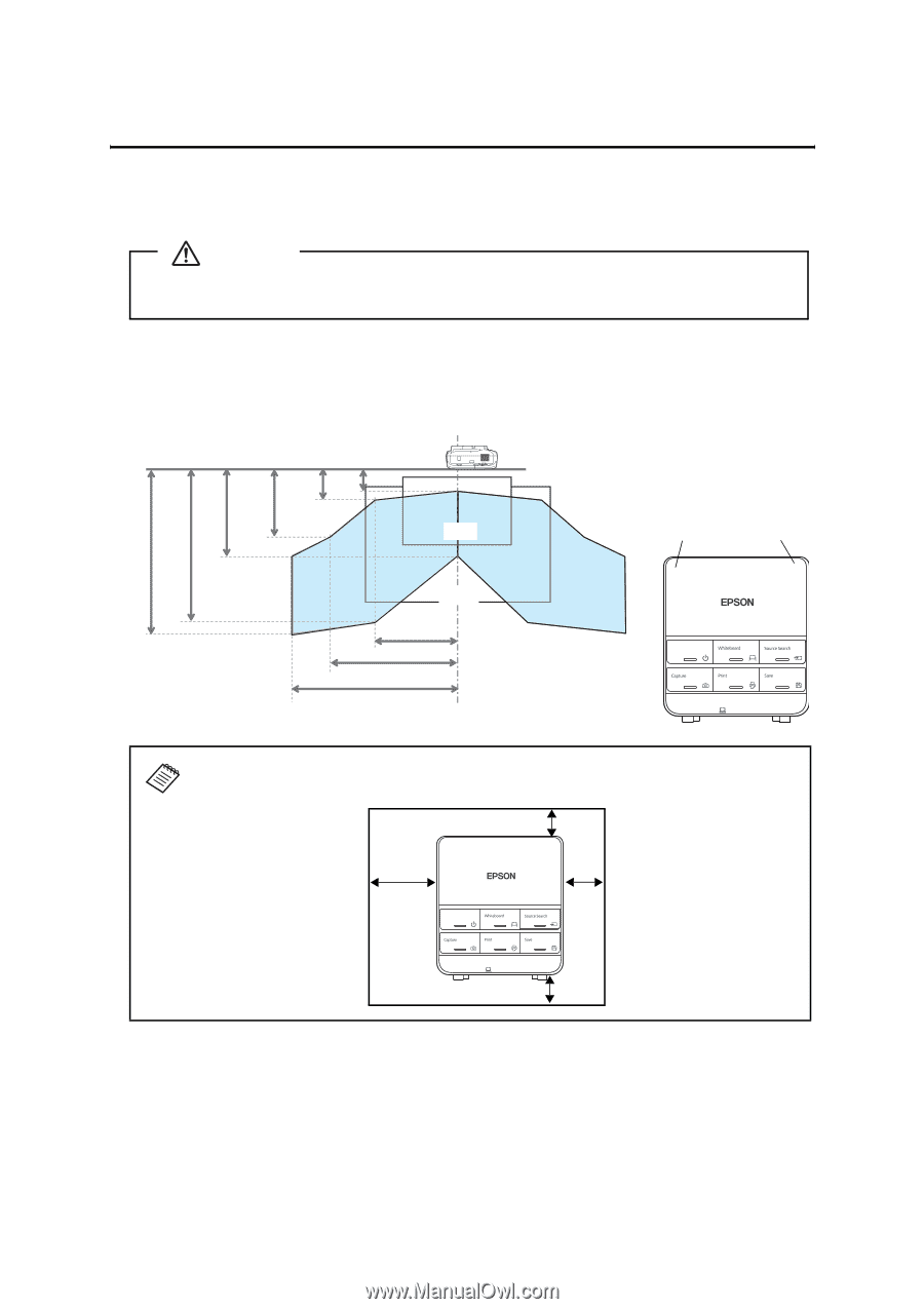
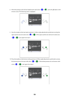
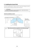
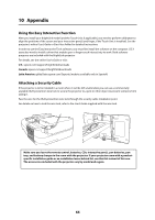
9 Installing the Control Pad You must have completed the steps in "Installing the Projector" on page 30 before installing the Control Pad. Follow the steps below to install the Control Pad and connect to the projector. Caution The Control Pad should only be connected to the BrightLink Pro 1410Wi/1420Wi/1430Wi. Do not connect the Control Pad to any other projectors. Check the installation location The Control Pad must be installed in the area specified in the diagram below. 78.7 in. 68.9 in. 35.4 in. 27.6 in. 13.8 in. 9.8 in. (2.0 m) (1.75 m) (0.9 m) (0.7 m) (0.35 m) (0.25 m) 60-inch image 100-inch image 39.3 in. (1.0 m) 59.0 in. (1.5 m) 78.7 in. (2.0 m) Remote control light emitting areas Make sure there is enough space surrounding the Control Pad. Because the top panel opens from the left, there must be additional space to the left of the Control Pad. 2 in (50 mm) 3.9 in (100 mm) 2 in (50 mm) 2 in (50 mm) 62
-
 1
1 -
2
-
3
-
4
-
5
-
6
-
7
-
8
-
9
-
10
-
11
-
12
-
13
-
14
-
15
-
16
-
17
-
18
-
19
-
20
-
21
-
22
-
23
-
24
-
25
-
26
-
27
-
28
-
29
-
30
-
31
-
32
-
33
-
34
-
35
-
36
-
37
-
38
-
39
-
40
-
41
-
42
-
43
-
44
-
45
-
46
-
47
-
48
-
49
-
50
-
51
-
52
-
53
-
54
-
55
-
56
-
 57
57 -
 58
58 -
 59
59 -
 60
60 -
 61
61 -
 62
62 -
 63
63 -
 64
64 -
 65
65 -
 66
66 -
 67
67 -
68
-
69
-
70
-
71
-
72
-
73
-
74
-
75
-
76
-
77
-
78
-
79
-
80
-
81
-
82
-
83
-
84
-
85
-
86
-
87
-
88
-
89
-
90
-
91
-
92
-
93
-
94
-
95
-
96
-
97
-
98
-
99
-
100
-
101
-
102
-
103
-
104
-
105
-
106
-
107
-
108
-
109
-
110
-
111
-
112
-
113
-
114
-
115
-
116
-
117
-
118
-
119
-
120
-
121
-
122
-
123
-
124
-
125
-
126
-
127
-
128
-
129
-
130
-
131
-
132
-
133
-
134
-
135
-
136
-
137
-
138
-
139
-
140
 |
 |