Epson 585Wi Installation Guide - Ultra-Short Throw Wall Mount (ELPMB43) - Page 19
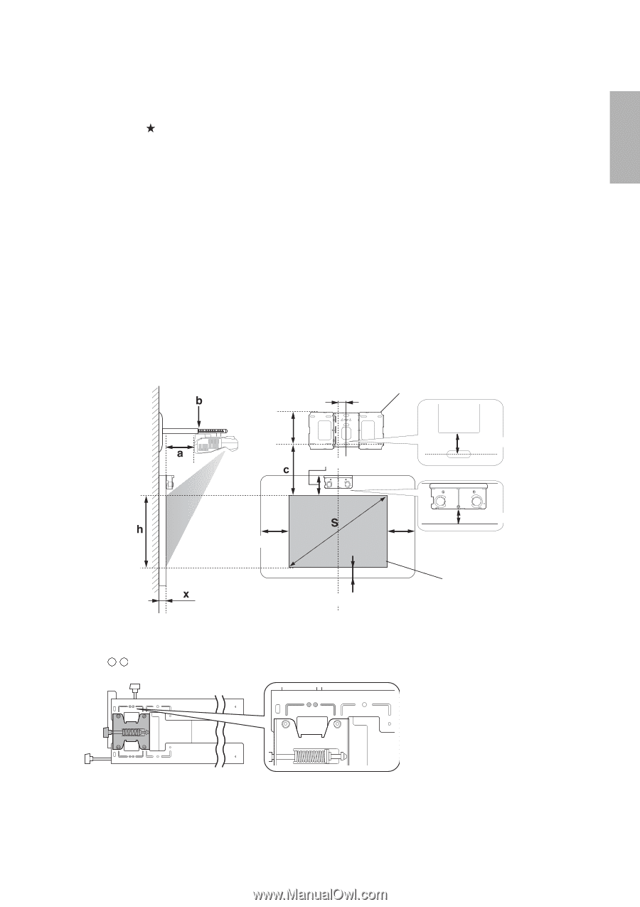
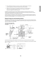
Diagonal image size and mounting position, When the diagonal image size is 75 inches or more
 |
View all Epson 585Wi manuals
Add to My Manuals
Save this manual to your list of manuals |
Page 19 highlights
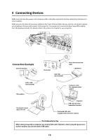
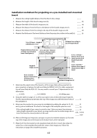
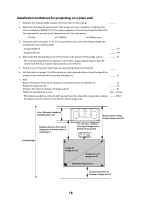
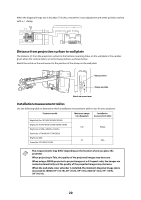
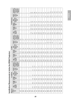
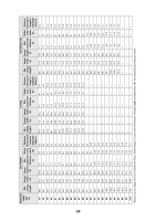
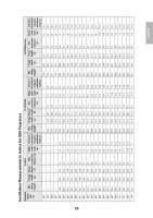
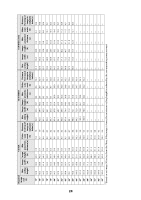
English 8. After confirming your image size, use tape or a pencil to mark the distance (c) from the top of the image area on the board to the bottom holes of the wall plate. 9. Align the line (horizontal) on the template sheet with the (c) mark, then align the center line on the template sheet with the center of the image area. Follow the instructions on page 30 to install the projector. The tables on the following pages provide installation information for all supported image sizes. The minimum ceiling height is based on an image 30 inches from the floor; if the image is lower, the minimum ceiling height is reduced by the corresponding measurement. Use the worksheets, the illustrations, and the information in the tables on the following pages to determine the projection distance and placement of the wall plate. The recommended range for projection distance (a) as shown on the following pages is 2.5 to 12.2 inches (62 to 311 mm). Diagonal image size and mounting position The numbers on the slider measure (b) are the same as the projection distance (a) when the diagonal image size (S) is 75 inches or more. Because the installation position of the projector changes when (S) is less than 75 inches, the numbers for (a) and (b) differ. Offset value for the position of the center of the screen and the center of the wall plate 2.8 in. (70.5 mm) Wall plate 8.6 in. (218 mm) 4.7 in. (120 mm) 1.2 in. (30.6 mm) Height of projected image 4.0 in. (100 mm) 1 in. (25 mm) Distance from wall to projection surface 0.8 in. (20 mm) Projection surface In order to see the stamp and the numbers on the slider scale, you need to slide out the arm extension. When the diagonal image size is 75 inches or more, mount the 3-axis adjustment unit at the position marked with a stamp. 19
-
 1
1 -
2
-
3
-
4
-
5
-
6
-
7
-
8
-
9
-
10
-
11
-
12
-
13
-
 14
14 -
 15
15 -
 16
16 -
 17
17 -
 18
18 -
 19
19 -
 20
20 -
 21
21 -
 22
22 -
 23
23 -
 24
24 -
25
-
26
-
27
-
28
-
29
-
30
-
31
-
32
-
33
-
34
-
35
-
36
-
37
-
38
-
39
-
40
-
41
-
42
-
43
-
44
-
45
-
46
-
47
-
48
-
49
-
50
-
51
-
52
-
53
-
54
-
55
-
56
-
57
-
58
-
59
-
60
-
61
-
62
-
63
-
64
-
65
-
66
-
67
-
68
-
69
-
70
-
71
-
72
-
73
-
74
-
75
-
76
-
77
-
78
-
79
-
80
-
81
-
82
-
83
-
84
-
85
-
86
-
87
-
88
-
89
-
90
-
91
-
92
-
93
-
94
-
95
-
96
-
97
-
98
-
99
-
100
-
101
-
102
-
103
-
104
-
105
-
106
-
107
-
108
-
109
-
110
-
111
-
112
-
113
-
114
-
115
-
116
-
117
-
118
-
119
-
120
-
121
-
122
-
123
-
124
-
125
-
126
-
127
-
128
-
129
-
130
-
131
-
132
-
133
-
134
-
135
-
136
-
137
-
138
-
139
-
140
 |
 |