Epson 585Wi Installation Guide - Ultra-Short Throw Wall Mount (ELPMB43) - Page 51
Determine the installation position for the Touch Unit
 |
View all Epson 585Wi manuals
Add to My Manuals
Save this manual to your list of manuals |
Page 51 highlights
English 2. Slide the dial cover down to remove it. 3. Remove the two markers from inside the Touch Unit. Use the markers to perform the angle adjustment (p. 53) after installing the Touch Unit. D Determine the installation position for the Touch Unit Mark the following installation positions: • ( ): The center line of the installation pattern; align it with the center line of the Touch Unit 1 inch (25 mm) from the top edge of the projected image; align with the bottom edge of the Touch Unit. 1.0 in. (25 mm) The Touch Unit must be installed above the image area. 51
-
 1
1 -
2
-
3
-
4
-
5
-
6
-
7
-
8
-
9
-
10
-
11
-
12
-
13
-
14
-
15
-
16
-
17
-
18
-
19
-
20
-
21
-
22
-
23
-
24
-
25
-
26
-
27
-
28
-
29
-
30
-
31
-
32
-
33
-
34
-
35
-
36
-
37
-
38
-
39
-
40
-
41
-
42
-
43
-
44
-
45
-
 46
46 -
 47
47 -
 48
48 -
 49
49 -
 50
50 -
 51
51 -
 52
52 -
 53
53 -
 54
54 -
 55
55 -
 56
56 -
57
-
58
-
59
-
60
-
61
-
62
-
63
-
64
-
65
-
66
-
67
-
68
-
69
-
70
-
71
-
72
-
73
-
74
-
75
-
76
-
77
-
78
-
79
-
80
-
81
-
82
-
83
-
84
-
85
-
86
-
87
-
88
-
89
-
90
-
91
-
92
-
93
-
94
-
95
-
96
-
97
-
98
-
99
-
100
-
101
-
102
-
103
-
104
-
105
-
106
-
107
-
108
-
109
-
110
-
111
-
112
-
113
-
114
-
115
-
116
-
117
-
118
-
119
-
120
-
121
-
122
-
123
-
124
-
125
-
126
-
127
-
128
-
129
-
130
-
131
-
132
-
133
-
134
-
135
-
136
-
137
-
138
-
139
-
140
 |
 |
51
English
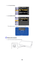
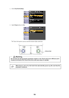
2.
Slide the dial cover down to remove it.
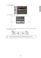
3.
Remove the two markers from inside the Touch Unit.
Use the markers to perform the angle adjustment (p. 53) after installing the Touch Unit.
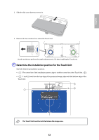
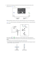
D
Determine the installation position for the Touch Unit
Mark the following installation positions:
•
(
): The center line of the installation pattern; align it with the center line of the Touch Unit (
).
•
(
): 1 inch (25 mm) from the top edge of the projected image; align with the bottom edge of the
Touch Unit.
The Touch Unit must be installed above the image area.
1.0 in. (25 mm)