HP ML115 HP ProLiant ML115 Generation 5 Server Maintenance and Service Guide - Page 32
Cable connections, Table 3, Cable, Cable Designator
 |
UPC - 884962252765
View all HP ML115 manuals
Add to My Manuals
Save this manual to your list of manuals |
Page 32 highlights
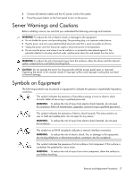
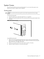
Figure 5 Unplugging power cables Cable connections The following table provides information about switching power supply cable connector labels. Table 3 Cable connections Cable Switching Power Supply Switching Power Supply Switching Power Supply Switching Power Supply Switching Power Supply Switching Power Supply Switching Power Supply Switching Power Supply Switching Power Supply Switching Power Supply Switching Power Supply Switching Power Supply To System board System board CPU power 1st SATA hard drive 2nd SATA hard drive 3rd SATA hard drive 4th SATA hard drive 1st SAS hard drive 2nd SAS hard drive 3rd SAS hard drive 4th SAS hard drive 1st optical drive 2nd optical drive Cable Designator P1 P2 P12 P10 P8 P6 P11 P9 P7 P5 P13 P14 The following table provides the system board designators that various cables plug into. For more detailed information about system board components, see System board components on page 62. Removal and Replacement Procedures 32
-
 1
1 -
2
-
3
-
4
-
5
-
6
-
7
-
8
-
9
-
10
-
11
-
12
-
13
-
14
-
15
-
16
-
17
-
18
-
19
-
20
-
21
-
22
-
23
-
24
-
25
-
26
-
 27
27 -
 28
28 -
 29
29 -
 30
30 -
 31
31 -
 32
32 -
 33
33 -
 34
34 -
 35
35 -
 36
36 -
 37
37 -
38
-
39
-
40
-
41
-
42
-
43
-
44
-
45
-
46
-
47
-
48
-
49
-
50
-
51
-
52
-
53
-
54
-
55
-
56
-
57
-
58
-
59
-
60
-
61
-
62
-
63
-
64
-
65
-
66
-
67
-
68
-
69
-
70
-
71
-
72
-
73
-
74
-
75
-
76
-
77
-
78
-
79
-
80
-
81
-
82
-
83
-
84
-
85
-
86
-
87
-
88
 |
 |
