HP ML115 HP ProLiant ML115 Generation 5 Server Maintenance and Service Guide - Page 48
If necessary, remove any accessory boards or cables that prevent access to the PCI slots.
 |
UPC - 884962252765
View all HP ML115 manuals
Add to My Manuals
Save this manual to your list of manuals |
Page 48 highlights
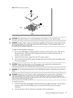
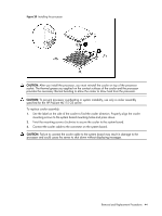
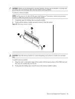
Figure 25 PCI slots location To remove the PCI slot cover lock: 1. Remove the retaining screw that secures the slot cover lock to the chassis. 2. Remove the slot cover lock from the chassis. 3. Remove the PCI bracket from the chassis. Figure 26 Removing the PCI slot cover lock NOTE: If necessary, remove any accessory boards or cables that prevent access to the PCI slots. CAUTION: Do not discard the PCI bracket. If the PCI expansion card is removed in the future, the PCI bracket must be reinstalled. Removal and Replacement Procedures 48
-
 1
1 -
2
-
3
-
4
-
5
-
6
-
7
-
8
-
9
-
10
-
11
-
12
-
13
-
14
-
15
-
16
-
17
-
18
-
19
-
20
-
21
-
22
-
23
-
24
-
25
-
26
-
27
-
28
-
29
-
30
-
31
-
32
-
33
-
34
-
35
-
36
-
37
-
38
-
39
-
40
-
41
-
42
-
 43
43 -
 44
44 -
 45
45 -
 46
46 -
 47
47 -
 48
48 -
 49
49 -
 50
50 -
 51
51 -
 52
52 -
 53
53 -
54
-
55
-
56
-
57
-
58
-
59
-
60
-
61
-
62
-
63
-
64
-
65
-
66
-
67
-
68
-
69
-
70
-
71
-
72
-
73
-
74
-
75
-
76
-
77
-
78
-
79
-
80
-
81
-
82
-
83
-
84
-
85
-
86
-
87
-
88
 |
 |

Removal and Replacement Procedures
48
Figure 25
PCI slots location
To remove the PCI slot cover lock:
1.
Remove the retaining screw that secures the slot cover lock to the chassis.
2.
Remove the slot cover lock from the chassis.
3.
Remove the PCI bracket from the chassis.
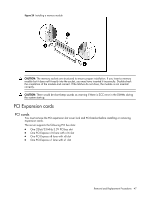
Figure 26
Removing the PCI slot cover lock
NOTE:
If necessary, remove any accessory boards or cables that prevent access to the PCI slots.
CAUTION:
Do not discard the PCI bracket. If the PCI expansion card is removed in the future, the
PCI bracket must be reinstalled.