HP ML115 HP ProLiant ML115 Generation 5 Server Maintenance and Service Guide - Page 61
Connectors, switches and LEDs, Connectors and components, Front panel components - g5 manual
 |
UPC - 884962252765
View all HP ML115 manuals
Add to My Manuals
Save this manual to your list of manuals |
Page 61 highlights
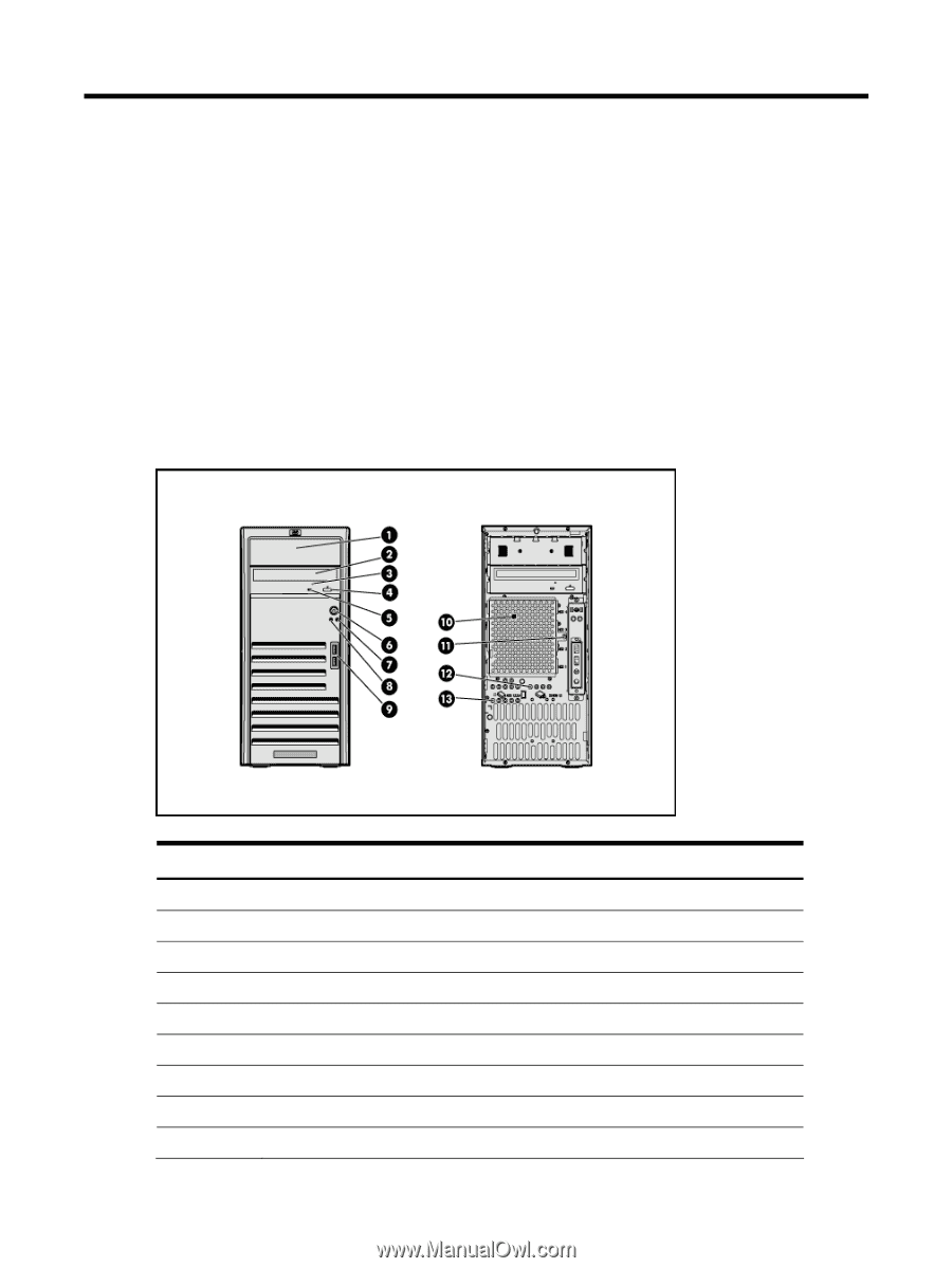
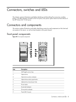
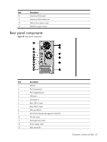
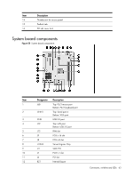
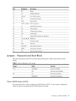
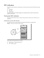
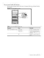
Connectors, switches and LEDs This chapter contains illustrations and tables identifying and describing the connectors, switches, buttons, and LED indicators located on the front panel, rear panel, system board and hard drives of the HP ProLiant ML115 G5 server. Connectors and components This section contains illustrations and tables identifying connectors and components on the front and rear panels of the server, as well as those located on the system board. Front panel components Figure 48 Front panel components Item 1 2 3 4 5 6 7 8 9 Description Half height common bay Optical drive Optical drive activity indicator Optical drive activity eject button Optical drive manual eject hole Power button Power LED indicator Drive activity indicator Front USB 2.0 ports Connectors, switches and LEDs 61
-
 1
1 -
2
-
3
-
4
-
5
-
6
-
7
-
8
-
9
-
10
-
11
-
12
-
13
-
14
-
15
-
16
-
17
-
18
-
19
-
20
-
21
-
22
-
23
-
24
-
25
-
26
-
27
-
28
-
29
-
30
-
31
-
32
-
33
-
34
-
35
-
36
-
37
-
38
-
39
-
40
-
41
-
42
-
43
-
44
-
45
-
46
-
47
-
48
-
49
-
50
-
51
-
52
-
53
-
54
-
55
-
 56
56 -
 57
57 -
 58
58 -
 59
59 -
 60
60 -
 61
61 -
 62
62 -
 63
63 -
 64
64 -
 65
65 -
 66
66 -
67
-
68
-
69
-
70
-
71
-
72
-
73
-
74
-
75
-
76
-
77
-
78
-
79
-
80
-
81
-
82
-
83
-
84
-
85
-
86
-
87
-
88
 |
 |