HP ML115 HP ProLiant ML115 Generation 5 Server Maintenance and Service Guide - Page 43
Applying too much grease creates a gap between the contact surfaces, significantly
 |
UPC - 884962252765
View all HP ML115 manuals
Add to My Manuals
Save this manual to your list of manuals |
Page 43 highlights
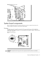
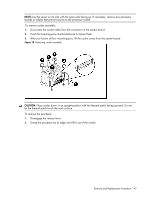
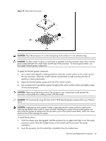
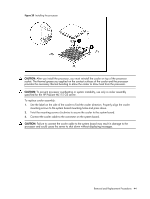
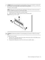
Figure 19 Removing the processor CAUTION: Place the processor on a static-dissipating work surface or in an anti-static bag. CAUTION: To allow cooler to draw as much heat as possible from the processor base, there must be good contact between the cooler base and the top of the processor. To ensure good contact, you must apply thermal grease compound. To apply the thermal grease compound: 1. Use a clean cloth dipped in rubbing alcohol to clean the contact surface on the cooler and on the new processor. Wipe the contact surfaces several times to make sure they are free of particles or dust contaminants. 2. Apply the thermal grease compound to the CPU contact surface. 3. Use a proper tool to spread the grease throughout the entire contact surface and lightly scrape off any excess grease. CAUTION: Never touch the bottom size of the processor; any contaminant could prevent the processor contact pads from making contact with the socket. CAUTION: HP recommends using Shin-Etsu X-23-7783D thermal grease compound for your ProLiant server. CAUTION: Applying too much grease creates a gap between the contact surfaces, significantly reducing the ability of the cooler to draw out heat. Installing the cooler with excessive grease can also cause the grease to spread over the processor pins or the system board base, which can cause electrical shorts that damage the system. To install the processor: 1. With the release lever disengaged, hold the processor by its edges and align it over the empty processor socket. Note the triangle locator on the socket and the processor for proper orientation. 2. Insert the processor into the socket then completely close the release lever. Removal and Replacement Procedures 43
-
 1
1 -
2
-
3
-
4
-
5
-
6
-
7
-
8
-
9
-
10
-
11
-
12
-
13
-
14
-
15
-
16
-
17
-
18
-
19
-
20
-
21
-
22
-
23
-
24
-
25
-
26
-
27
-
28
-
29
-
30
-
31
-
32
-
33
-
34
-
35
-
36
-
37
-
 38
38 -
 39
39 -
 40
40 -
 41
41 -
 42
42 -
 43
43 -
 44
44 -
 45
45 -
 46
46 -
 47
47 -
 48
48 -
49
-
50
-
51
-
52
-
53
-
54
-
55
-
56
-
57
-
58
-
59
-
60
-
61
-
62
-
63
-
64
-
65
-
66
-
67
-
68
-
69
-
70
-
71
-
72
-
73
-
74
-
75
-
76
-
77
-
78
-
79
-
80
-
81
-
82
-
83
-
84
-
85
-
86
-
87
-
88
 |
 |
