HP ML115 HP ProLiant ML115 Generation 5 Server Maintenance and Service Guide - Page 37
rear of the chassis and then push the drive all the way into the chassis until the drive clicks
 |
UPC - 884962252765
View all HP ML115 manuals
Add to My Manuals
Save this manual to your list of manuals |
Page 37 highlights
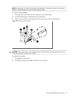
Figure 10 Removing the optical drive shield 2. Install the new optical drive. a. Fasten four screws (two on each side) into the new optical drive. b. Slide the new optical drive into the bay, with the cable connectors of the drive facing the rear of the chassis and then push the drive all the way into the chassis until the drive clicks into place. c. Connect the power and data cables to the connectors on the rear of the drive. Figure 11 Installing an optional media drive Removal and Replacement Procedures 37
-
 1
1 -
2
-
3
-
4
-
5
-
6
-
7
-
8
-
9
-
10
-
11
-
12
-
13
-
14
-
15
-
16
-
17
-
18
-
19
-
20
-
21
-
22
-
23
-
24
-
25
-
26
-
27
-
28
-
29
-
30
-
31
-
 32
32 -
 33
33 -
 34
34 -
 35
35 -
 36
36 -
 37
37 -
 38
38 -
 39
39 -
 40
40 -
 41
41 -
 42
42 -
43
-
44
-
45
-
46
-
47
-
48
-
49
-
50
-
51
-
52
-
53
-
54
-
55
-
56
-
57
-
58
-
59
-
60
-
61
-
62
-
63
-
64
-
65
-
66
-
67
-
68
-
69
-
70
-
71
-
72
-
73
-
74
-
75
-
76
-
77
-
78
-
79
-
80
-
81
-
82
-
83
-
84
-
85
-
86
-
87
-
88
 |
 |

Removal and Replacement Procedures
37
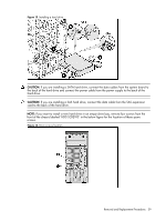
Figure 10
Removing the optical drive shield
2.
Install the new optical drive.
a.
Fasten four screws (two on each side) into the new optical drive.
b.
Slide the new optical drive into the bay, with the cable connectors of the drive facing the
rear of the chassis and then push the drive all the way into the chassis until the drive clicks
into place.
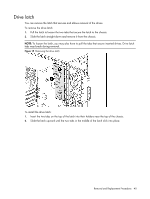
c.
Connect the power and data cables to the connectors on the rear of the drive.
Figure 11
Installing an optional media drive