HP ML115 HP ProLiant ML115 Generation 5 Server Maintenance and Service Guide - Page 39
If you are installing a SAS hard drive, connect the data cable from the SAS expansion
 |
UPC - 884962252765
View all HP ML115 manuals
Add to My Manuals
Save this manual to your list of manuals |
Page 39 highlights
Figure 13 Installing a hard drive CAUTION: If you are installing a SATA hard drive, connect the data cables from the system board to the back of the hard drive and connect the power cable from the power supply to the back of the hard drive. CAUTION: If you are installing a SAS hard drive, connect the data cable from the SAS expansion card to the back of the hard drive. NOTE: If you want to install a new hard drive in an empty drive bay, remove four screws from the front of the chassis labeled 'HDD SCREWS' in the below figure for the location of these spare screws. Figure 14 Drive screws location Removal and Replacement Procedures 39
-
 1
1 -
2
-
3
-
4
-
5
-
6
-
7
-
8
-
9
-
10
-
11
-
12
-
13
-
14
-
15
-
16
-
17
-
18
-
19
-
20
-
21
-
22
-
23
-
24
-
25
-
26
-
27
-
28
-
29
-
30
-
31
-
32
-
33
-
 34
34 -
 35
35 -
 36
36 -
 37
37 -
 38
38 -
 39
39 -
 40
40 -
 41
41 -
 42
42 -
 43
43 -
 44
44 -
45
-
46
-
47
-
48
-
49
-
50
-
51
-
52
-
53
-
54
-
55
-
56
-
57
-
58
-
59
-
60
-
61
-
62
-
63
-
64
-
65
-
66
-
67
-
68
-
69
-
70
-
71
-
72
-
73
-
74
-
75
-
76
-
77
-
78
-
79
-
80
-
81
-
82
-
83
-
84
-
85
-
86
-
87
-
88
 |
 |

Removal and Replacement Procedures
39
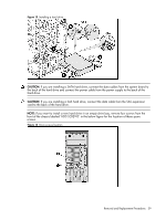
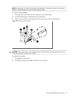
Figure 13
Installing a hard drive
CAUTION:
If you are installing a SATA hard drive, connect the data cables from the system board to
the back of the hard drive and connect the power cable from the power supply to the back of the
hard drive.
CAUTION:
If you are installing a SAS hard drive, connect the data cable from the SAS expansion
card to the back of the hard drive.
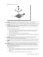
NOTE:
If you want to install a new hard drive in an empty drive bay, remove four screws from the
front of the chassis labeled ‘HDD SCREWS’ in the below figure for the location of these spare
screws.
Figure 14
Drive screws location