HP Tc4100 hp server tc4100 operation and maintenance guide (English, 2.1) - Page 107
Installing the Hot Swap Drive Cage Backplane., Replacing the Fan Assembly
 |
View all HP Tc4100 manuals
Add to My Manuals
Save this manual to your list of manuals |
Page 107 highlights
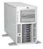
Chapter 7 Replacing Parts 12. Release the mount plate from the chassis by first raising it up slightly out of the lower slot, and then swinging it out towards the rear of the server and lifting it out of the chassis. See Figure 7-3.. Captive screw Jumper Cable SCSI Mgmt. Board Figure 7-3. Hot Swap Drive Cage Backplane Removal 13. Place the mount plate on a work surface and disconnect the SCSI jumper cable, if installed, and either one or two hot-swap drive cage management boards (terminators), which ever is applicable. 14. Locate and remove the eight Torx 15 screws, four per side, that are attaching the backplane to the mount plate. Installing the Hot Swap Drive Cage Backplane. 1. Install the new backplane to the mount plate by securing it with the eight Torx 15 screws. 2. To reinstall it in the chassis, align the mount plate into the metal rail and slide the mount plate into position, making sure that all cables are out of the way. Secure the mount plate to the chassis with the blue thumbscrew. 3. Reverse the steps listed above to reassemble the server. NOTE When installing the fan cage, be very careful to move all cables out of the way so they don't get pinched when sliding the fan cage in on the rails. When installing the fan assembly, make sure the SCSI cable is not over the connector where the fan assembly plugs in. Replacing the Fan Assembly Replace the Fan Assembly when the system indicates slow or failing fans. The fans are contained in a single replaceable module enclosed in the fan tray. The fan tray and the attached air scoop are removed to upgrade system board parts, remove the system board, or access power and signal cables. 105
-
 1
1 -
2
-
3
-
4
-
5
-
6
-
7
-
8
-
9
-
10
-
11
-
12
-
13
-
14
-
15
-
16
-
17
-
18
-
19
-
20
-
21
-
22
-
23
-
24
-
25
-
26
-
27
-
28
-
29
-
30
-
31
-
32
-
33
-
34
-
35
-
36
-
37
-
38
-
39
-
40
-
41
-
42
-
43
-
44
-
45
-
46
-
47
-
48
-
49
-
50
-
51
-
52
-
53
-
54
-
55
-
56
-
57
-
58
-
59
-
60
-
61
-
62
-
63
-
64
-
65
-
66
-
67
-
68
-
69
-
70
-
71
-
72
-
73
-
74
-
75
-
76
-
77
-
78
-
79
-
80
-
81
-
82
-
83
-
84
-
85
-
86
-
87
-
88
-
89
-
90
-
91
-
92
-
93
-
94
-
95
-
96
-
97
-
98
-
99
-
100
-
101
-
 102
102 -
 103
103 -
 104
104 -
 105
105 -
 106
106 -
 107
107 -
 108
108 -
 109
109 -
 110
110 -
 111
111 -
 112
112 -
113
-
114
-
115
-
116
-
117
-
118
-
119
-
120
-
121
-
122
-
123
-
124
-
125
-
126
-
127
-
128
-
129
-
130
 |
 |
