HP Tc4100 hp server tc4100 operation and maintenance guide (English, 2.1) - Page 43
Memory Board, Notch, places, Align Keys, with Notches, Close Retaining, Latches, Retaining Latches
 |
View all HP Tc4100 manuals
Add to My Manuals
Save this manual to your list of manuals |
Page 43 highlights
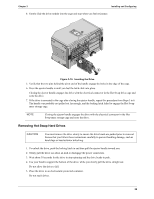
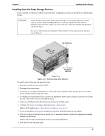
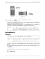
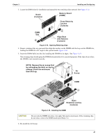
Chapter 3 Installing and Configuring 3. Locate the DIMM slot for installation and spread the two retaining clips outward. See Figure 3-14. Notch (2 places) Memory Board (DIMM) DIMM Slot 2 Close Retaining Latches (2 places) 1 2 Align Keys with Notches (2 places) Figure 3-14. Opening Retaining Clips 4. Ensure retaining clips are open and then align the notches on the DIMM with the keys on the DIMM slot, holding the DIMM at a 90° angle to the system board. Figure 3-14. 5. Insert the DIMM fully into the slot, handling the DIMM by its edges. See Figure 3-15. The retaining clips should grasp the DIMM automatically if it is inserted properly. If the clips do not close, the DIMM is not inserted correctly. NOTE: Remove the air scoop first by unhooking the latch on top to release it from fan enclosure then lift it up. Air 1 Scoop DIMM 3 2 2 Open Retaining Latches (2 places) Figure 3-15. Installing the DIMM CAUTION Do not rock the DIMM into place, but apply firm and even pressure. If the retaining clips do not close, remove the DIMM and repeat Steps 5-6 6. Re-install the Air Scoop. 41
-
 1
1 -
2
-
3
-
4
-
5
-
6
-
7
-
8
-
9
-
10
-
11
-
12
-
13
-
14
-
15
-
16
-
17
-
18
-
19
-
20
-
21
-
22
-
23
-
24
-
25
-
26
-
27
-
28
-
29
-
30
-
31
-
32
-
33
-
34
-
35
-
36
-
37
-
 38
38 -
 39
39 -
 40
40 -
 41
41 -
 42
42 -
 43
43 -
 44
44 -
 45
45 -
 46
46 -
 47
47 -
 48
48 -
49
-
50
-
51
-
52
-
53
-
54
-
55
-
56
-
57
-
58
-
59
-
60
-
61
-
62
-
63
-
64
-
65
-
66
-
67
-
68
-
69
-
70
-
71
-
72
-
73
-
74
-
75
-
76
-
77
-
78
-
79
-
80
-
81
-
82
-
83
-
84
-
85
-
86
-
87
-
88
-
89
-
90
-
91
-
92
-
93
-
94
-
95
-
96
-
97
-
98
-
99
-
100
-
101
-
102
-
103
-
104
-
105
-
106
-
107
-
108
-
109
-
110
-
111
-
112
-
113
-
114
-
115
-
116
-
117
-
118
-
119
-
120
-
121
-
122
-
123
-
124
-
125
-
126
-
127
-
128
-
129
-
130
 |
 |
