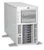
HP Tc4100 hp server tc4100 operation and maintenance guide (English, 2.1) - Page 50
Re-install the Air Scoop., Installing Heat Sink
 |
View all HP Tc4100 manuals
Add to My Manuals
Save this manual to your list of manuals |
Page 50 highlights
Chapter 3 Installing and Configuring • Spread the grease carefully over the core using a single-edge razor blade or some other tool as long as the tool is clean. Don't allow the grease to spread beyond the edges of the core rectangle • Center the heat sink properly over the additional processor • Locate the bottom notched edge of the heat sink and, when placing the heat sink over the processor, be sure that the notched edge faces the front panel of the HP Server tc4100. CAUTION Minimize any twisting or lateral sliding when installing the heat sink on the processor. Ensure you have made good contact with the processor to avoid thermal overheating. If you have not made good contact with the processor, it will overheat within 20 seconds of power on and will shut down. Lower Clip Tab 4 To Hook Latch in Back 1 Unplug 2 Power Cord 5 Lower Clip Tab To Hook Latch in Front 3 Align Latch holes with processor Socket tab Processor Tab (2 places) Figure 3-19. Installing Heat Sink NOTE Before the processor heat sink can be latched on, the Air Scoop must be removed from the fan wall. If you do not remove the Air Scoop, the front heat sink clip can not be accessed. 13. Fasten the rear heat sink clip by matching the holes of the clips with the tabs of the socket. 14. Fasten the front heat sink clip in the same fashion. 15. Re-install the Air Scoop. 16. Re-install the cover and bezel onto the Server according to the appropriate procedure. Refer to "Opening and Closing the HP Server tc4100" on page 21. 17. Return power to the Server and restore normal operation. 48
-
 1
1 -
2
-
3
-
4
-
5
-
6
-
7
-
8
-
9
-
10
-
11
-
12
-
13
-
14
-
15
-
16
-
17
-
18
-
19
-
20
-
21
-
22
-
23
-
24
-
25
-
26
-
27
-
28
-
29
-
30
-
31
-
32
-
33
-
34
-
35
-
36
-
37
-
38
-
39
-
40
-
41
-
42
-
43
-
44
-
 45
45 -
 46
46 -
 47
47 -
 48
48 -
 49
49 -
 50
50 -
 51
51 -
 52
52 -
 53
53 -
 54
54 -
 55
55 -
56
-
57
-
58
-
59
-
60
-
61
-
62
-
63
-
64
-
65
-
66
-
67
-
68
-
69
-
70
-
71
-
72
-
73
-
74
-
75
-
76
-
77
-
78
-
79
-
80
-
81
-
82
-
83
-
84
-
85
-
86
-
87
-
88
-
89
-
90
-
91
-
92
-
93
-
94
-
95
-
96
-
97
-
98
-
99
-
100
-
101
-
102
-
103
-
104
-
105
-
106
-
107
-
108
-
109
-
110
-
111
-
112
-
113
-
114
-
115
-
116
-
117
-
118
-
119
-
120
-
121
-
122
-
123
-
124
-
125
-
126
-
127
-
128
-
129
-
130
 |
 |
