HP d248 HP Compaq Business Desktop d200 Series Personal Computers Service Refe - Page 26
Drive Installation Guidelines, Single-Drive Cable, Two-Drive Cable
 |
View all HP d248 manuals
Add to My Manuals
Save this manual to your list of manuals |
Page 26 highlights
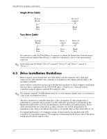
Ultra ATA Drive Guidelines and Features Single-Drive Cable System Board Device 0 (master) Blue Face Two-Drive Cable System Board Black Face Device 1 (slave) Device 0 (master) Blue Gray Black Face Face Face On a two-drive cable, the Drive/Device 0 connector is always the farthest one from the system board connector and the Drive/Device 1 connector is always the closest to the system board connector. ✎ Some cables may be labeled "Drive 0" instead of "Device 0" and "Drive 1" instead of "Device 1". 4.3 Drive Installation Guidelines Most computer system boards have two ATA (IDE) controller channels with a dedicated connector for each controller. One controller is designated as the primary and the other as the secondary controller. Each of the two controllers can have up to two devices attached to it. Each computer system may therefore have a maximum of four ATA/ATAPI drives. All drives are connected to these controllers using an industry-standard 80-conductor cable. ✎ The industry standard 1.44 MB diskette drive has its own separate channel and is not included as a part of the maximum four drives. Any drive attached to a controller must have a drive designation. If only a single drive is connected to a controller and its jumper is in the cable-select position, it is designated as the Master Drive (Drive/Device 0) by its attachment to the Drive/Device 0 cable position. If two cable-selected drives are connected to a single controller, one will be designated by its attachment to the cable as the Master (Drive/Device 0) and the other as Slave (Drive/Device 1). For optimal performance of a computer system, all drives need to be attached to the ATA controllers in a specified sequence. This sequence is determined by the device class of the drives and by specific attach sequence rules. 4-2 336493-004 Service Reference Guide, d200
-
 1
1 -
2
-
3
-
4
-
5
-
6
-
7
-
8
-
9
-
10
-
11
-
12
-
13
-
14
-
15
-
16
-
17
-
18
-
19
-
20
-
 21
21 -
 22
22 -
 23
23 -
 24
24 -
 25
25 -
 26
26 -
 27
27 -
 28
28 -
 29
29 -
 30
30 -
 31
31 -
32
-
33
-
34
-
35
-
36
-
37
-
38
-
39
-
40
-
41
-
42
-
43
-
44
-
45
-
46
-
47
-
48
-
49
-
50
-
51
-
52
-
53
-
54
-
55
-
56
-
57
-
58
-
59
-
60
-
61
-
62
-
63
-
64
-
65
-
66
-
67
-
68
-
69
-
70
-
71
-
72
-
73
-
74
-
75
-
76
-
77
-
78
-
79
-
80
-
81
-
82
-
83
-
84
-
85
-
86
-
87
-
88
-
89
-
90
-
91
-
92
-
93
-
94
-
95
-
96
-
97
-
98
-
99
-
100
-
101
-
102
-
103
-
104
-
105
-
106
-
107
-
108
-
109
-
110
 |
 |
