Hitachi HDS728080PLAT20 Specifications - Page 115
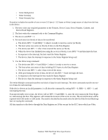
For the Write Long command
 |
UPC - 829686000094
View all Hitachi HDS728080PLAT20 manuals
Add to My Manuals
Save this manual to your list of manuals |
Page 115 highlights
• Write Multiple Ext • Write Sector(s) • Write Sector(s) Ext Execution includes the transfer of one or more 512 byte (> 512 bytes on Write Long) sectors of data from the host to the device. 1. The host writes any required parameters to the Features, Sector Count, Sector Number, Cylinder, and Device/Head Registers. 2. The host writes the command code to the Command Register. 3. The device sets BSY = 1. 4. For each sector (or block) of data to be transferred: a. The devics BSY = 0 and DRQ = 1 when it is ready to receive a sector (or block). b. The host writes one sector (or block) of data via the Data Register. c. The device sets BSY = 1 after it has received the sector (or block). d. When the device has finished processing the sector (or block), it sets BSY = 0 and interrupts the host. e. In response to the interrupt, the host reads the Status Register. f. The device clears the interrupt in response to the Status Register being read. 5. For the Write Long command: a. The device sets BSY = 0 and DRQ = 1 when it is ready to receive a sector. b. The host writes one sector of data including ECC bytes via the Data Register. c. The device sets BSY = 1 after it has received the sector. d. After processing the sector of data, the device sets BSY = 0 and interrupts the host. e. In response to the interrupt the host reads the Status Register. f. The device clears the interrupt in response to the Status Register being read. The Write Multiple command transfers one block of data for each interrupt. The other commands transfer one sector of data for each interrupt. If the device detects an invalid parameter, it will abort the command by setting BSY = 0, ERR = 1, ABT = 1, and interrupting the host. If an uncorrectable error occurs, the device will set BSY = 0 and ERR = 1, store the error status in the Error Register, and interrupt the host. The registers will contain the location of the sector in error. The errored location will be reported with CHS mode or LBA mode. The mode is decided by the mode select bit (bit 6) of the Device/Head register on issuing the command. All data transfers to the device through the Data Register are 16 bits except for the ECC bytes which are 8 bits. Deskstar 7K80 Hard Disk Drive Specification 111
-
 1
1 -
2
-
3
-
4
-
5
-
6
-
7
-
8
-
9
-
10
-
11
-
12
-
13
-
14
-
15
-
16
-
17
-
18
-
19
-
20
-
21
-
22
-
23
-
24
-
25
-
26
-
27
-
28
-
29
-
30
-
31
-
32
-
33
-
34
-
35
-
36
-
37
-
38
-
39
-
40
-
41
-
42
-
43
-
44
-
45
-
46
-
47
-
48
-
49
-
50
-
51
-
52
-
53
-
54
-
55
-
56
-
57
-
58
-
59
-
60
-
61
-
62
-
63
-
64
-
65
-
66
-
67
-
68
-
69
-
70
-
71
-
72
-
73
-
74
-
75
-
76
-
77
-
78
-
79
-
80
-
81
-
82
-
83
-
84
-
85
-
86
-
87
-
88
-
89
-
90
-
91
-
92
-
93
-
94
-
95
-
96
-
97
-
98
-
99
-
100
-
101
-
102
-
103
-
104
-
105
-
106
-
107
-
108
-
109
-
 110
110 -
 111
111 -
 112
112 -
 113
113 -
 114
114 -
 115
115 -
 116
116 -
 117
117 -
 118
118 -
 119
119 -
 120
120 -
121
-
122
-
123
-
124
-
125
-
126
-
127
-
128
-
129
-
130
-
131
-
132
-
133
-
134
-
135
-
136
-
137
-
138
-
139
-
140
-
141
-
142
-
143
-
144
-
145
-
146
-
147
-
148
-
149
-
150
-
151
-
152
-
153
-
154
-
155
-
156
-
157
-
158
-
159
-
160
-
161
-
162
-
163
-
164
-
165
-
166
-
167
-
168
-
169
-
170
-
171
-
172
-
173
-
174
-
175
-
176
-
177
-
178
-
179
-
180
-
181
-
182
-
183
-
184
-
185
-
186
-
187
-
188
-
189
-
190
-
191
-
192
-
193
-
194
-
195
-
196
-
197
-
198
-
199
-
200
-
201
-
202
-
203
-
204
-
205
-
206
-
207
-
208
-
209
-
210
-
211
-
212
-
213
-
214
-
215
-
216
-
217
-
218
-
219
-
220
-
221
-
222
-
223
-
224
-
225
-
226
-
227
-
228
-
229
-
230
-
231
-
232
-
233
-
234
-
235
-
236
-
237
-
238
-
239
-
240
-
241
-
242
-
243
-
244
-
245
-
246
-
247
-
248
-
249
-
250
-
251
-
252
-
253
-
254
-
255
-
256
-
257
-
258
 |
 |