Hitachi HDS728080PLAT20 Specifications - Page 58
Jumper pin assignment, Jumper positions - as a slave
 |
UPC - 829686000094
View all Hitachi HDS728080PLAT20 manuals
Add to My Manuals
Save this manual to your list of manuals |
Page 58 highlights
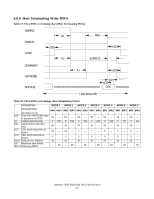
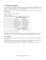
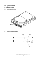
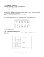
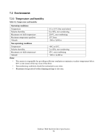
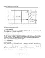
7.1.3 Jumper pin assignment There are four jumper settings as shown in the following sections: • 16 logical head default (normal use) • 15 logical head default • 32 GB clip • Power up in standby Within each of these four jumper settings the pin assignment selects Device 0, Device 1, Cable Selection, or Device 1 Slave Present as shown in the following figures. The Device 0 setting automatically recognizes device 1 if it is present. The Device 1 Slave Present setting is for a slave device that does not comply with the ATA specification. Note: In conventional terminology "Device 0" designates a Master and "Device 1" designates a Slave. RSV GND GND GND RSV I GECA HFDB DS CS/SP GND RSV 7.1.4 Jumper positions 7.1.4.1 16 logical head default (normal use) The figure below shows the jumper positions used to select Device 0, Device 1, Cable Selection, or Device1 (Slave) Present. IGECA H F D B IGECA HFDB IGECA HFDB IGECA HFDB IGECA H F D B DEVICE 0 (Master) DEVICE 1 (Slave) CABLE SEL DEVICE 1 (Slave) Present Shipping Default Condition (DEVICE 0) Deskstar 7K80 Hard Disk Drive Specification 54
-
 1
1 -
2
-
3
-
4
-
5
-
6
-
7
-
8
-
9
-
10
-
11
-
12
-
13
-
14
-
15
-
16
-
17
-
18
-
19
-
20
-
21
-
22
-
23
-
24
-
25
-
26
-
27
-
28
-
29
-
30
-
31
-
32
-
33
-
34
-
35
-
36
-
37
-
38
-
39
-
40
-
41
-
42
-
43
-
44
-
45
-
46
-
47
-
48
-
49
-
50
-
51
-
52
-
 53
53 -
 54
54 -
 55
55 -
 56
56 -
 57
57 -
 58
58 -
 59
59 -
 60
60 -
 61
61 -
 62
62 -
 63
63 -
64
-
65
-
66
-
67
-
68
-
69
-
70
-
71
-
72
-
73
-
74
-
75
-
76
-
77
-
78
-
79
-
80
-
81
-
82
-
83
-
84
-
85
-
86
-
87
-
88
-
89
-
90
-
91
-
92
-
93
-
94
-
95
-
96
-
97
-
98
-
99
-
100
-
101
-
102
-
103
-
104
-
105
-
106
-
107
-
108
-
109
-
110
-
111
-
112
-
113
-
114
-
115
-
116
-
117
-
118
-
119
-
120
-
121
-
122
-
123
-
124
-
125
-
126
-
127
-
128
-
129
-
130
-
131
-
132
-
133
-
134
-
135
-
136
-
137
-
138
-
139
-
140
-
141
-
142
-
143
-
144
-
145
-
146
-
147
-
148
-
149
-
150
-
151
-
152
-
153
-
154
-
155
-
156
-
157
-
158
-
159
-
160
-
161
-
162
-
163
-
164
-
165
-
166
-
167
-
168
-
169
-
170
-
171
-
172
-
173
-
174
-
175
-
176
-
177
-
178
-
179
-
180
-
181
-
182
-
183
-
184
-
185
-
186
-
187
-
188
-
189
-
190
-
191
-
192
-
193
-
194
-
195
-
196
-
197
-
198
-
199
-
200
-
201
-
202
-
203
-
204
-
205
-
206
-
207
-
208
-
209
-
210
-
211
-
212
-
213
-
214
-
215
-
216
-
217
-
218
-
219
-
220
-
221
-
222
-
223
-
224
-
225
-
226
-
227
-
228
-
229
-
230
-
231
-
232
-
233
-
234
-
235
-
236
-
237
-
238
-
239
-
240
-
241
-
242
-
243
-
244
-
245
-
246
-
247
-
248
-
249
-
250
-
251
-
252
-
253
-
254
-
255
-
256
-
257
-
258
 |
 |
