Hitachi HDS728080PLAT20 Specifications - Page 180
Read Stream PIO 2Bh
 |
UPC - 829686000094
View all Hitachi HDS728080PLAT20 manuals
Add to My Manuals
Save this manual to your list of manuals |
Page 180 highlights
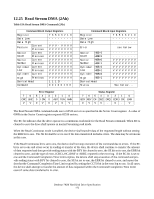
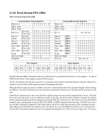
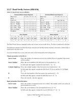
12.26 Read Stream PIO (2Bh) Table 120: Read Stream PIO (2Bh) Command Block Output Registers Register 7 6 5 4 3 2 1 0 Data Low Data High Current Feature Previous V V V - V V V V V V V V V V V V Sector Count Current Previous V V V V V V V V V V V V V V V V Sector Number Current Previous V V V V V V V V V V V V V V V V Cylinder Current Low Previous V V V V V V V V V V V V V V V V Cylinder Current V V V V V V V V High Previous V V V V V V V V Device/Head 1 1 1 D - - - - Command 0 0 1 0 0 1 0 0 76 CRC UNC VV Error Register 54 3 2 1 0 0 IDN 0 ABT T0N AMN 0V 0 V 0 V Command Block Input Registers Register 7 6 5 4 3 2 1 0 Data Low Data High Error see below Sector Count HOB=0 HOB=1 Sector Number HOB=0 HOB=1 Cylinder HOB=0 Low HOB=1 Cylinder HOB=0 High HOB=1 Device/Head Status V V V V V V V V V V V V V V V V V V V V V V V V V V V V V V V V V V V V V V V V V V V V V V V V See below ... Status Register 7 654 3 2 1 0 BSY RDY DF DSC DRQ COR IDX ERR 0 VVV - 0 - V The Read Stream DMA command reads one to 65536 sectors as specified in the Sector Count register. A value of 0000h in the Sector Count register requests 65536 sectors. The RC bit indicates that the drive operate in a continuous read mode for the Read Stream command. When RC is cleared to zero the drive shall operate in normal Streaming read mode. When the Read Continuous mode is enabled, the device shall transfer data of the requested length without setting the ERR bit. The SE bit shall be set to one if the data transferred includes errors. The data may be erroneous in this case. If the Read Continuous bit is set to one, the device shall not stop execution of the command due to errors. If the RC bit is set to one and errors occur in reading or transfer of the data, the device shall continue to transfer the amount of data requested and then provide ending status with the BSY bit cleared to zero, the SE bit set to one, the ERR bit cleared to zero, and the type of error, ICRC,UNC,IDNF, or ABRT, reported in the error log. If the RC bit is set to one and the Command Completion Time Limit expires, the device shall stop execution of the command and provide ending status with BSY bit cleared to zero, the SE bit set to one, the ERR bit cleared to zero, and report the fact that the Command Completion Time Limit expired by setting the CCTO bit in the error log to one, In all cases, Deskstar 7K80 Hard Disk Drive Specification 176
-
 1
1 -
2
-
3
-
4
-
5
-
6
-
7
-
8
-
9
-
10
-
11
-
12
-
13
-
14
-
15
-
16
-
17
-
18
-
19
-
20
-
21
-
22
-
23
-
24
-
25
-
26
-
27
-
28
-
29
-
30
-
31
-
32
-
33
-
34
-
35
-
36
-
37
-
38
-
39
-
40
-
41
-
42
-
43
-
44
-
45
-
46
-
47
-
48
-
49
-
50
-
51
-
52
-
53
-
54
-
55
-
56
-
57
-
58
-
59
-
60
-
61
-
62
-
63
-
64
-
65
-
66
-
67
-
68
-
69
-
70
-
71
-
72
-
73
-
74
-
75
-
76
-
77
-
78
-
79
-
80
-
81
-
82
-
83
-
84
-
85
-
86
-
87
-
88
-
89
-
90
-
91
-
92
-
93
-
94
-
95
-
96
-
97
-
98
-
99
-
100
-
101
-
102
-
103
-
104
-
105
-
106
-
107
-
108
-
109
-
110
-
111
-
112
-
113
-
114
-
115
-
116
-
117
-
118
-
119
-
120
-
121
-
122
-
123
-
124
-
125
-
126
-
127
-
128
-
129
-
130
-
131
-
132
-
133
-
134
-
135
-
136
-
137
-
138
-
139
-
140
-
141
-
142
-
143
-
144
-
145
-
146
-
147
-
148
-
149
-
150
-
151
-
152
-
153
-
154
-
155
-
156
-
157
-
158
-
159
-
160
-
161
-
162
-
163
-
164
-
165
-
166
-
167
-
168
-
169
-
170
-
171
-
172
-
173
-
174
-
 175
175 -
 176
176 -
 177
177 -
 178
178 -
 179
179 -
 180
180 -
 181
181 -
 182
182 -
 183
183 -
 184
184 -
 185
185 -
186
-
187
-
188
-
189
-
190
-
191
-
192
-
193
-
194
-
195
-
196
-
197
-
198
-
199
-
200
-
201
-
202
-
203
-
204
-
205
-
206
-
207
-
208
-
209
-
210
-
211
-
212
-
213
-
214
-
215
-
216
-
217
-
218
-
219
-
220
-
221
-
222
-
223
-
224
-
225
-
226
-
227
-
228
-
229
-
230
-
231
-
232
-
233
-
234
-
235
-
236
-
237
-
238
-
239
-
240
-
241
-
242
-
243
-
244
-
245
-
246
-
247
-
248
-
249
-
250
-
251
-
252
-
253
-
254
-
255
-
256
-
257
-
258
 |
 |
