Hitachi HDS728080PLAT20 Specifications - Page 151
Read DMA C8h/C9h
 |
UPC - 829686000094
View all Hitachi HDS728080PLAT20 manuals
Add to My Manuals
Save this manual to your list of manuals |
Page 151 highlights
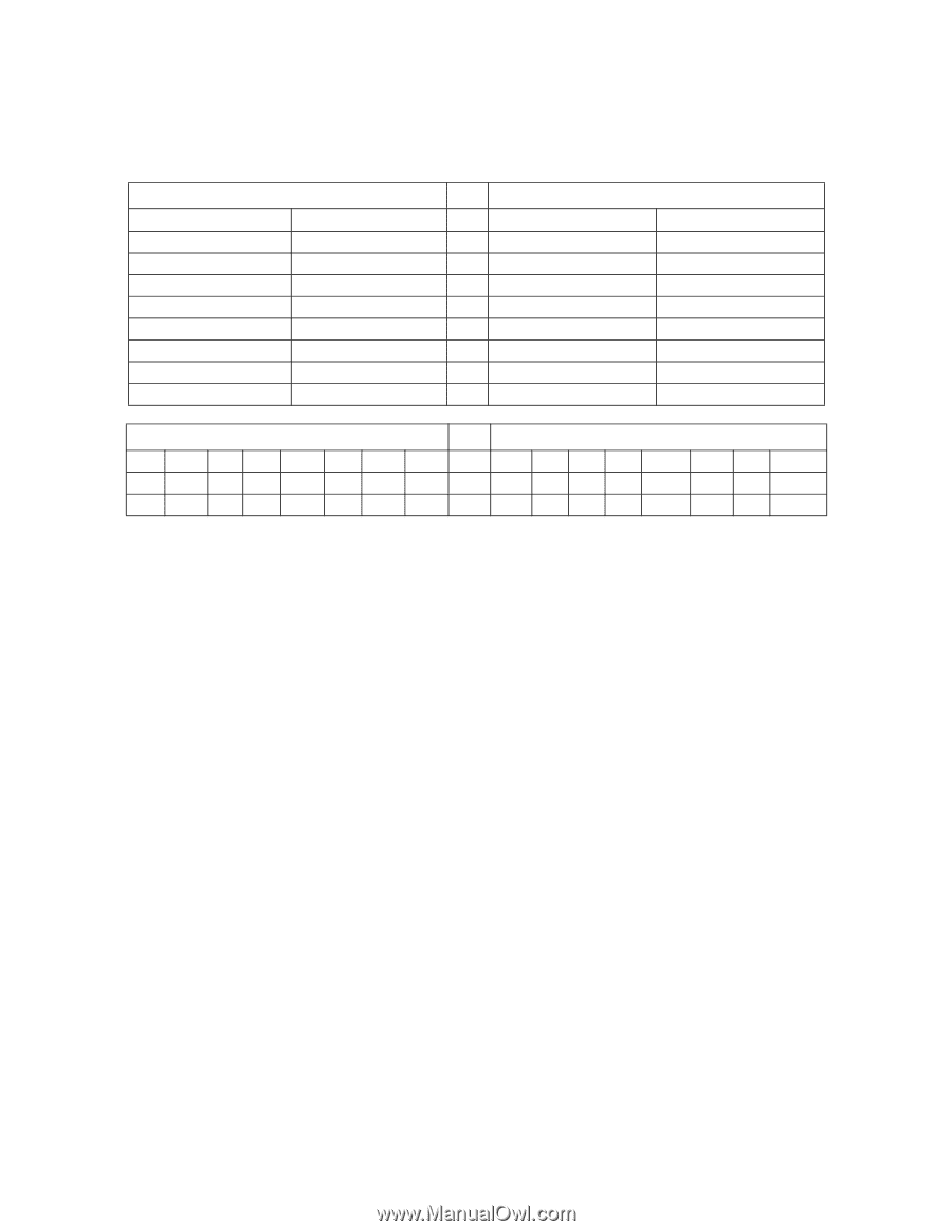
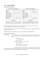
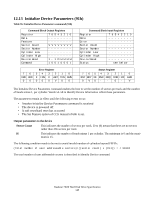
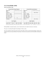
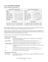
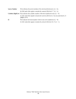
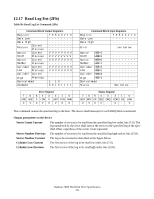
12.15 Read DMA (C8h/C9h) Table 97: Read DMA command (C8h/C9h) Command Block Output Registers Register 7 6 5 4 3 2 1 0 Data Feature Sector Count V V V V V V V V Sector Number V V V V V V V V Cylinder Low V V V V V V V V Cylinder High V V V V V V V V Device/Head 1 L 1 D H H H H Command 1 1 0 0 1 0 0 R 76 CRC UNC VV Error Register 54 3 2 1 0 0 IDN 0 ABT T0N AMN 0V 0 V 0 0 Command Block Input Registers Register 7 6 5 4 3 2 1 0 Data Error see below Sector Count V V V V V V V V Sector Number V V V V V V V V Cylinder Low V V V V V V V V Cylinder High V V V V V V V V Device/Head - - - - H H H H Status see below Status Register 7 654 3 2 1 0 BSY RDY DF DSC DRQ COR IDX ERR 0 V0V - 0 - V The Read DMA command reads one or more sectors of data from disk media and then transfers the data from the device to the host. It transfers the sectors through the Data Register 16 bits at a time. The host initializes a slave-DMA channel prior to issuing the command. The data transfers are qualified by the DMARQ and are performed by the slave-DMA channel. The device issues only one interrupt per command to indicate that the data transfer has terminated and that status is available. If an uncorrectable error occurs, the read will be terminated at the failing sector. Output parameters to the device Sector Count This indicates the number of continuous sectors to be transferred. If zero is specified, 256 sectors will be transferred. Sector Number This indicates the sector number of the first sector to be transferred. (L = 0). In LBA mode, this register specifies the transfer of LBA address bits 0-7. (L = 1) Cylinder High/Low This indicates the cylinder number of the first sector to be transferred. (L = 0). In LBA mode, this register specifies the transfer of LBA address bits 8-15 (Low) and 16- 23 (High). (L = 1) H This indicates the head number of the first sector to be transferred. (L = 0). In LBA mode this register specifies that LBA bits 24-27 is to be transferred. (L = 1) R This indicates the retry bit. This bit is ignored. Input parameters from the device Sector Count This indicates the number of requested sectors not transferred. This will be zero, unless an unrecoverable error occurs. Deskstar 7K80 Hard Disk Drive Specification 147
-
 1
1 -
2
-
3
-
4
-
5
-
6
-
7
-
8
-
9
-
10
-
11
-
12
-
13
-
14
-
15
-
16
-
17
-
18
-
19
-
20
-
21
-
22
-
23
-
24
-
25
-
26
-
27
-
28
-
29
-
30
-
31
-
32
-
33
-
34
-
35
-
36
-
37
-
38
-
39
-
40
-
41
-
42
-
43
-
44
-
45
-
46
-
47
-
48
-
49
-
50
-
51
-
52
-
53
-
54
-
55
-
56
-
57
-
58
-
59
-
60
-
61
-
62
-
63
-
64
-
65
-
66
-
67
-
68
-
69
-
70
-
71
-
72
-
73
-
74
-
75
-
76
-
77
-
78
-
79
-
80
-
81
-
82
-
83
-
84
-
85
-
86
-
87
-
88
-
89
-
90
-
91
-
92
-
93
-
94
-
95
-
96
-
97
-
98
-
99
-
100
-
101
-
102
-
103
-
104
-
105
-
106
-
107
-
108
-
109
-
110
-
111
-
112
-
113
-
114
-
115
-
116
-
117
-
118
-
119
-
120
-
121
-
122
-
123
-
124
-
125
-
126
-
127
-
128
-
129
-
130
-
131
-
132
-
133
-
134
-
135
-
136
-
137
-
138
-
139
-
140
-
141
-
142
-
143
-
144
-
145
-
 146
146 -
 147
147 -
 148
148 -
 149
149 -
 150
150 -
 151
151 -
 152
152 -
 153
153 -
 154
154 -
 155
155 -
 156
156 -
157
-
158
-
159
-
160
-
161
-
162
-
163
-
164
-
165
-
166
-
167
-
168
-
169
-
170
-
171
-
172
-
173
-
174
-
175
-
176
-
177
-
178
-
179
-
180
-
181
-
182
-
183
-
184
-
185
-
186
-
187
-
188
-
189
-
190
-
191
-
192
-
193
-
194
-
195
-
196
-
197
-
198
-
199
-
200
-
201
-
202
-
203
-
204
-
205
-
206
-
207
-
208
-
209
-
210
-
211
-
212
-
213
-
214
-
215
-
216
-
217
-
218
-
219
-
220
-
221
-
222
-
223
-
224
-
225
-
226
-
227
-
228
-
229
-
230
-
231
-
232
-
233
-
234
-
235
-
236
-
237
-
238
-
239
-
240
-
241
-
242
-
243
-
244
-
245
-
246
-
247
-
248
-
249
-
250
-
251
-
252
-
253
-
254
-
255
-
256
-
257
-
258
 |
 |