Hitachi HDS728080PLAT20 Specifications - Page 64
Power supply current typical, Power supply generated ripple at drive power connector - hard drive model
 |
UPC - 829686000094
View all Hitachi HDS728080PLAT20 manuals
Add to My Manuals
Save this manual to your list of manuals |
Page 64 highlights
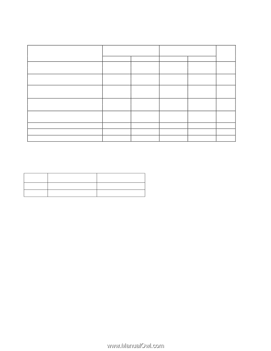
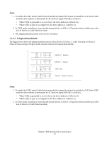
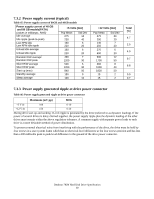
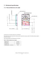
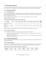
7.3.2 Power supply current (typical) Table 45: Power supply current of 80GB and 40GB models Power supply current of 40 GB and 80 GB models(PATA) (values in milliamps. RMS) Idle average Idle ripple (peak-to-peak) Low RPM idle Low RPM idle ripple Unload idle average Unload idle ripple Random R/W average1 Random R/W peak +5 Volts [mA] Pop Mean 275 230 160 220 160 220 490 1200 Std Dev 14 40 6 20 6 20 7 30 Silent R/W average Silent R/W peak Start up (max) Standby average Sleep average 500 6 1200 30 840 50 150 9 100 10 +12 Volts [mA] Pop Mean 275 290 140 250 270 400 600 1700 360 1000 1830 15 15 Std Dev 24 20 7 20 6 20 12 50 8 40 50 2 2 Total [W] 4.7 2.5 4.0 9.7 6.8 0.9 0.7 7.3.3 Power supply generated ripple at drive power connector Table 46: Power supply generated ripple at drive power connector Maximum (mV pp) MHz +5 V dc 100 0-10 +12 V dc 150 0-10 During drive start up and seeking 12-volt ripple is generated by the drive (referred to as dynamic loading). If the power of several drives is daisy chained together, the power supply ripple plus the dynamic loading of the other drives must remain within the above regulation tolerance. A common supply with separate power leads to each drive is a more desirable method of power distribution. To prevent external electrical noise from interfering with the performance of the drive, the drive must be held by four screws in a user system frame which has no electrical level difference at the four screws position and has less than ±300 millivolts peak to peak level difference to the ground of the drive power connector. Deskstar 7K80 Hard Disk Drive Specification 60
-
 1
1 -
2
-
3
-
4
-
5
-
6
-
7
-
8
-
9
-
10
-
11
-
12
-
13
-
14
-
15
-
16
-
17
-
18
-
19
-
20
-
21
-
22
-
23
-
24
-
25
-
26
-
27
-
28
-
29
-
30
-
31
-
32
-
33
-
34
-
35
-
36
-
37
-
38
-
39
-
40
-
41
-
42
-
43
-
44
-
45
-
46
-
47
-
48
-
49
-
50
-
51
-
52
-
53
-
54
-
55
-
56
-
57
-
58
-
 59
59 -
 60
60 -
 61
61 -
 62
62 -
 63
63 -
 64
64 -
 65
65 -
 66
66 -
 67
67 -
 68
68 -
 69
69 -
70
-
71
-
72
-
73
-
74
-
75
-
76
-
77
-
78
-
79
-
80
-
81
-
82
-
83
-
84
-
85
-
86
-
87
-
88
-
89
-
90
-
91
-
92
-
93
-
94
-
95
-
96
-
97
-
98
-
99
-
100
-
101
-
102
-
103
-
104
-
105
-
106
-
107
-
108
-
109
-
110
-
111
-
112
-
113
-
114
-
115
-
116
-
117
-
118
-
119
-
120
-
121
-
122
-
123
-
124
-
125
-
126
-
127
-
128
-
129
-
130
-
131
-
132
-
133
-
134
-
135
-
136
-
137
-
138
-
139
-
140
-
141
-
142
-
143
-
144
-
145
-
146
-
147
-
148
-
149
-
150
-
151
-
152
-
153
-
154
-
155
-
156
-
157
-
158
-
159
-
160
-
161
-
162
-
163
-
164
-
165
-
166
-
167
-
168
-
169
-
170
-
171
-
172
-
173
-
174
-
175
-
176
-
177
-
178
-
179
-
180
-
181
-
182
-
183
-
184
-
185
-
186
-
187
-
188
-
189
-
190
-
191
-
192
-
193
-
194
-
195
-
196
-
197
-
198
-
199
-
200
-
201
-
202
-
203
-
204
-
205
-
206
-
207
-
208
-
209
-
210
-
211
-
212
-
213
-
214
-
215
-
216
-
217
-
218
-
219
-
220
-
221
-
222
-
223
-
224
-
225
-
226
-
227
-
228
-
229
-
230
-
231
-
232
-
233
-
234
-
235
-
236
-
237
-
238
-
239
-
240
-
241
-
242
-
243
-
244
-
245
-
246
-
247
-
248
-
249
-
250
-
251
-
252
-
253
-
254
-
255
-
256
-
257
-
258
 |
 |