Hitachi HDS728080PLAT20 Specifications - Page 30
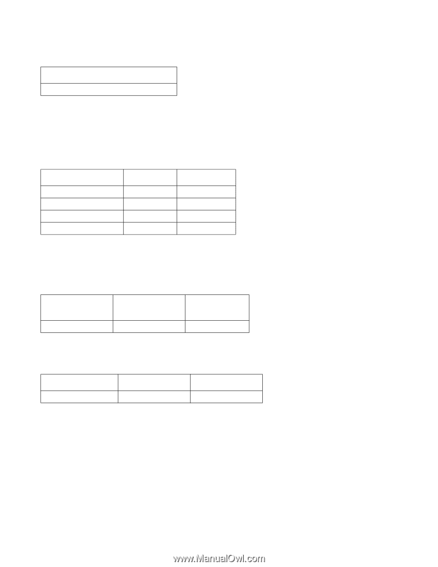
Drive ready time - diagnostic
 |
UPC - 829686000094
View all Hitachi HDS728080PLAT20 manuals
Add to My Manuals
Save this manual to your list of manuals |
Page 30 highlights
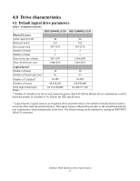
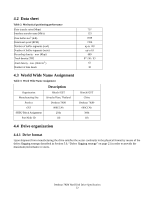
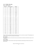
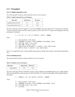
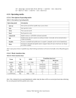
4.5.2.4 Cylinder switch time (cylinder skew) Cylinder switch time - typical (ms) 1.6 Cylinder switch time is defined as the amount of time required by the fixed disk to access the next sequential block after reading the last sector in the current cylinder. The measuring method is given in Section 4.5.5, "Throughput" on page 28. 4.5.2.5 Single track seek time (without command overhead, including settling) Table 9: Single track seek time Function Typical (ms) Read 0.8 Write 1.3 Read (Quiet Seek mode) 0.8 Write (Quiet Seek mode) 1.3 Max (ms) 1.5 2.0 1.5 2.0 Single track seek is measured as the average of one (1) single track seek from every track in both directions (inward and outward). 4.5.2.6 Average latency Table 10: Latency Time Rotational speed (RPM) 7200 RPM Time for one revolution (ms) 8.3 Average latency (ms) 4.17 4.5.3 Drive ready time Table 11: Drive ready time Power on to ready Typical (sec) 6 Maximum (sec) 20 Ready Power on The condition in which the drive is able to perform a media access command (for example- read, write) immediately. This includes the time required for the internal self diagnostics. Note: Max Power On to ready time is the maximum time period that Device 0 waits for Device 1 to assert PDIAG. Deskstar 7K80 Hard Disk Drive Specification 26
-
 1
1 -
2
-
3
-
4
-
5
-
6
-
7
-
8
-
9
-
10
-
11
-
12
-
13
-
14
-
15
-
16
-
17
-
18
-
19
-
20
-
21
-
22
-
23
-
24
-
 25
25 -
 26
26 -
 27
27 -
 28
28 -
 29
29 -
 30
30 -
 31
31 -
 32
32 -
 33
33 -
 34
34 -
 35
35 -
36
-
37
-
38
-
39
-
40
-
41
-
42
-
43
-
44
-
45
-
46
-
47
-
48
-
49
-
50
-
51
-
52
-
53
-
54
-
55
-
56
-
57
-
58
-
59
-
60
-
61
-
62
-
63
-
64
-
65
-
66
-
67
-
68
-
69
-
70
-
71
-
72
-
73
-
74
-
75
-
76
-
77
-
78
-
79
-
80
-
81
-
82
-
83
-
84
-
85
-
86
-
87
-
88
-
89
-
90
-
91
-
92
-
93
-
94
-
95
-
96
-
97
-
98
-
99
-
100
-
101
-
102
-
103
-
104
-
105
-
106
-
107
-
108
-
109
-
110
-
111
-
112
-
113
-
114
-
115
-
116
-
117
-
118
-
119
-
120
-
121
-
122
-
123
-
124
-
125
-
126
-
127
-
128
-
129
-
130
-
131
-
132
-
133
-
134
-
135
-
136
-
137
-
138
-
139
-
140
-
141
-
142
-
143
-
144
-
145
-
146
-
147
-
148
-
149
-
150
-
151
-
152
-
153
-
154
-
155
-
156
-
157
-
158
-
159
-
160
-
161
-
162
-
163
-
164
-
165
-
166
-
167
-
168
-
169
-
170
-
171
-
172
-
173
-
174
-
175
-
176
-
177
-
178
-
179
-
180
-
181
-
182
-
183
-
184
-
185
-
186
-
187
-
188
-
189
-
190
-
191
-
192
-
193
-
194
-
195
-
196
-
197
-
198
-
199
-
200
-
201
-
202
-
203
-
204
-
205
-
206
-
207
-
208
-
209
-
210
-
211
-
212
-
213
-
214
-
215
-
216
-
217
-
218
-
219
-
220
-
221
-
222
-
223
-
224
-
225
-
226
-
227
-
228
-
229
-
230
-
231
-
232
-
233
-
234
-
235
-
236
-
237
-
238
-
239
-
240
-
241
-
242
-
243
-
244
-
245
-
246
-
247
-
248
-
249
-
250
-
251
-
252
-
253
-
254
-
255
-
256
-
257
-
258
 |
 |